Freestanding cooker OR60 models Installation instructions and User guide NZ AU
Contents Safety and warnings Installation instructions - GAS COOKTOP MODELS Installation instructions - CERAMIC GLASS COOKTOP MODELS 1 2 6 15 FOUR-FUNCTION MODELS WITH GAS COOKTOP Using your oven for the first time Using your oven Cooking functions Using your gas cooktop Cooktop troubleshooting Care and cleaning 20 21 22 23 27 28 SEVEN-FUNCTION MODELS WITH GAS COOKTOP Using your oven for the first time Oven controls and setting the clock Cooking functions Using the electronic timer Automatic cooking
2 Safety and warnings Installation WARNING! Electrical Shock Hazard Always disconnect the cooker from the mains electricity supply before carrying out any maintenance operations or repairs. Models with ceramic glass cooktop: If the ceramic glass cooktop surface becomes cracked, switch the appliance off at the mains power supply and call an Authorised Service Agent. Failure to do so may result in death or electrical shock. WARNING! Cut Hazard Take care - panel edges are sharp.
Safety and warnings 3 Electrical This cooker is to be installed and connected to the electricity supply only by an authorised person. If the installation requires alterations to the domestic electrical system, call a qualified electrician. The electrician should also check that the electrical system is suitable for the electricity drawn by the cooker.
4 Safety and warnings Operation Your freestanding cooker has been carefully designed to operate safely during normal cooking procedures. Please keep the following guidelines in mind when you are using it: WARNING! Explosion Hazard Do not store flammable materials such as gasoline near the cooktop. Do not store flammable material in the oven or drawer. Do not spray aerosols near the cooktop during use. Failure to follow this advice may result in death or serious injury.
Safety and warnings 5 Important safety instructions Never leave the appliance unattended when in use. Boilover causes smoking and greasy spillovers that may ignite. Isolating switch: make sure this cooker is connected to a circuit which incorporates an isolating switch providing full disconnection from the power supply. Household appliances are not intended to be played with by children.
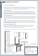
6 Installation instructions Installation clearances and protection of combustible surfaces shall comply with the current local regulations eg. AG 601 (AS 5601/NZS 5261) Gas Installations code. Installation shall comply with the dimensions in Fig. 1, bearing in mind the following requirements: Overhead Clearances In no case shall the clearance above the highest part of the cooker be less than 600 mm or, for an overhead exhaust fan, 750 mm.
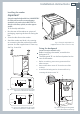
Installation instructions 7 Levelling the cooker 1 2 3 Using the supplied adjustable feet is MANDATORY. For safety reasons and to ensure adequate ventilation, the cooker chassis MUST NOT sit directly on the floor, a plinth, or other support surface. To fit the adjustable feet: Rest the rear of the cooker on a piece of packaging, exposing the base for fitting the feet. Screw the four feet to the cooker. Stand the cooker and level it by screwing or unscrewing the feet with an adjustable spanner.
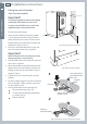
8 Installation instructions 600 mm (Cavity width ) Important! To restrain the appliance and prevent it tipping accidentally, fit a bracket to its rear to fix it securely to the wall. Make sure you also fit the supplied lock pin to the anti-tiit bracket. 1 2 To fit the anti-tilt bracket: After you have located where the cooker is to be positioned, mark on the wall the place where the two screws of the anti-tilt bracket have to be fitted. Please follow the indications given in Fig.5a.
Installation instructions 9 Important! To restrain the appliance and prevent it tipping accidentally, fit a bracket to its rear to fix it securely to the wall. Make sure you also fit the supplied lock pin to the anti-tiit bracket. = = 75 1 2 To fit the anti-tilt bracket: After you have located where the cooker is to be positioned, mark on the wall the place where the two screws of the anti-tilt bracket have to be fitted. Please follow the indications given in Fig.6a.
10 Installation instructions FOURCOOKTOP GAS FUNCTION MODELS MODELS Connecting the cooker to the gas supply The gas connection must be carried out by an authorised person according to the relevant standards. Before connecting the appliance to the gas main, mount the brass conical adaptor onto the gas inlet pipe, upon which the washer has been placed (see Figs. 7-8 following). Conical adaptor and washer are supplied with the appliance (packed with conversion kit for use with Natural gas or LPG).
Installation instructions It is important that the hose does not come in contact with the metal of the appliance and is secured as per appropriate gas installation codes. A chain 80% of the length of the flexible gas hose must be used to prevent stress being applied to the hose. The chain should be attached securely to the product where shown (see Fig.10), and on the wall. Flexible hose assemblies should be AS/NZS 1869 Class B or Class D certified. The thread connection shall be Rp ½” (ISO 7-1) male.
12 Installation instructions FOURCOOKTOP GAS FUNCTION MODELS MODELS Converting to a different gas type This appliance is suitable for use with Natural gas or LPG (check the “gas type” sticker attached to the appliance). To convert from one gas type to another, you need to replace the injectors, and then adjust the minimum burner setting. 1 2 3 4 Replacing the injectors Remove the trivets and burners from the cooktop. Using a spanner, remove the injector (shown in Figs.
Installation instructions 13 1 2 3 4 Check whether the flame spreads to all burner ports when the burner is lit with the gas valve set to the minimum position. If some ports do not light, increase the minimum gas rate setting. Check whether the burner remains lit even when the gas valve is turned quickly from the maximum to the minimum position. If the burner does not remain lit, increase the minimum gas rate setting. To adjust the minimum gas rate setting: Turn on the burner.
14 Installation instructions FOURCOOKTOP GAS FUNCTION MODELS MODELS Wiring diagram - Four-function models Cod.
15 Dimensions and clearances 500 mm 450 mm 650 mm The cooker must be installed at least 50 mm away from any side walls higher than the cooktop. The cabinetry surrounding the cooker must be made of heat-resistant material and must be able to withstand temperatures of 65 °C above room temperature. Do not install the cooker near flammable materials (eg curtains). If you stand the cooker on a pedestal, make sure you provide safety measures to keep it in place.
FOUR FUNCTION CERAMIC GLASS COOKTOP MODELS MODELS 16 Installation instructions Levelling the cooker Important! 1 2 3 Using the supplied adjustable feet is MANDATORY. For safety reasons and to ensure adequate ventilation, the cooker chassis MUST NOT sit directly on the floor, a plinth, or other support surface. To fit the adjustable feet: Rest the rear of the cooker on a piece of packaging, exposing the base for fitting the feet. Screw the four feet to the cooker.
17 Dotted line showing the position of the cooker when installed Fitting the anti-tilt bracket Important! To restrain the appliance and prevent it tipping accidentally, fit a bracket to its rear to fix it securely to the wall. Make sure you also fit the supplied lock pin to the anti-tiit bracket. = 1 2 To fit the anti-tilt bracket: After you have located where the cooker is to be positioned, mark on the wall the place where the two screws of the anti-tilt bracket have to be fitted.
Installation instructions Connecting the power supply cable Important! This cooker must be connected to the electricity supply only by an authorised person. To connect the power supply cable to the cooker, it is necessary to: 1 2 3 4 5 6 Remove the screws that hold cover “A” behind the cooker (Fig. 19b). Position the U bolts “C” onto five-pole terminal block “B” according to the diagram in Fig. 19a. Feed the power supply cable through the cable clamp “D”.
CF LF V 5 6 7 8 9 10 11 5a 6a 8a 9a 10a 11a S G C 7a CIR ELECTRIC DIAGRAM KEY F1 Oven switch F4/5 Energy regulators (single zones) F2/3 Energy regulators (double zones) LF Oven lamp TM Oven thermostat TS Safety thermostat PR Electronic programmer TL 4 4a 3a 2a 1 2 3 1a C G S V CIR CR S1 TS 1a 1 L/8 N/7 M 2 S H 4 4A S2 4 P1 2 S1 P2 1 2 3 4 5 P1 4a Top heating element Grill heating element Bottom heating element Fan motor Circular heating element Residual heat lam
20 Using your oven for the first time Front left (auxiliary) burner knob FOUR-FUNCTIONFOUR MODELS FUNCTION WITH GAS MODELS COOKTOP Temperature indicator light Function Temperature knob knob Rear right (semirapid) burner knob Rear left (semi-rapid) Front right burner knob (triple-ring wok) burner knob Fig. 20 Control panel 1 2 3 Before using your new oven, please: Read this user guide, taking special note of the ‘Safety and warnings’ section. Remove all accessories and packaging.
21 Fig. 22 Function and temperature knobs 1 2 3 Select the function by turning the function knob. The oven light will come on. Select the temperature by turning the temperature control knob clockwise. The oven temperature indicator light, above the oven control knobs on the control panel, will glow until the oven has reached the set temperature, and then it will go out. Note: the temperature indicator light may glow and go out again during cooking as the oven maintains the set temperature.
FOUR-FUNCTIONFOUR MODELS FUNCTION WITH GAS MODELS COOKTOP 22 Cooking functions OVEN LAMP Only the oven light comes on. It remains on in all the cooking functions. BAKE The upper and lower heating elements come on. BAKE is the traditional method of cooking. It is best to cook on only one shelf at a time in this function. Ideal for large cakes and dishes that bake for several hours. FAN BAKE The upper and lower heating elements and the fan come on.
23 FOUR-FUNCTIONFOUR MODELS FUNCTION WITH GAS MODELS COOKTOP Using your gas cooktop 2 2 1 3 Fig. 24 Cooktop layout 1 2 3 Auxiliary burner Semi-rapid burner Triple-ring wok burner Gas burners The knob controls the flow of gas through the safety valve. 0 = closed valve (OFF) = maximum flow = minimum flow You can choose to cook at any heat between and , but never between Fig. 25 Burner control knob and 0 (OFF).
24 Using your gas cooktop FOUR-FUNCTIONFOUR MODELS FUNCTION WITH GAS MODELS COOKTOP Before using your cooktop Before using your new cooktop, please: Read this user guide, taking special note of the ‘Safety and warnings’ section. Turn the power to the cooker on at the wall. Make sure all controls are turned off. Using the gas burners 1 2 3 Choose the control knob for the burner you want to use. Press the knob down gently and turn it anticlockwise to the position.
Using your gas cooktop 25 Check that: The cooker is plugged in and the electricity is switched on. The gas is turned on. The gas bottle is not empty (if you are using bottled gas). The ignitors are sparking. If the ignitors are not sparking, they may be dirty or wet. Clean them with a toothbrush and methylated spirits, as shown in Fig. 26. Ignitor Fig.
26 Using your gas cooktop FOUR-FUNCTIONFOUR MODELS FUNCTION WITH GAS MODELS COOKTOP Matching cookware to burner Use flat-bottomed pans, and make sure they match the size of the burner, as shown in the following table. A small pot on a large burner is not efficient. Diameters of pans which may be used on the cooktop Burners Minimum Maximum Auxiliary 12 cm (6 cm with small pan support) 14 cm Semi-rapid 16 cm 24 cm Triple-ring wok 26 cm 28 cm Maximum diameter for woks 36 cm Fig.
Problem Possible solutions A burner does not light. Check the cooker is switched on at the wall. Check the gas supply valve is turned on and the supply to the house is working. You should hear the gas when you turn a burner on. Check the gas bottle is not empty. The ignitors may be dirty. Clean them with a toothbrush and methylated spirits. The burner parts may not be located properly. Check the assembly and make sure the burner cap is sitting flat. My burner flames are yellow or hard to start.
28 Care and cleaning FOUR-FUNCTIONFOUR MODELS FUNCTION WITH GAS MODELS COOKTOP Important! Before you start cleaning your cooker, please: Read these cleaning instructions and the ‘Safety and warnings’ section at the start of this user guide. Turn the power to the cooker off at the wall. Make sure the cooker is a safe temperature to touch. Do not use a steam cleaner. Do not keep flammable substances in the oven. General advice Wipe down the cooktop and wipe out the oven after every use. Wipe up spills.
29 Burner parts and trivets You can remove and clean these parts with hot soapy water or non-abrasive detergents. Clean spills regularly before they become burnt on. Do not wash these parts in a dishwasher. After cleaning, check that the burners and their flame spreaders are dry before replacing correctly. It is very important to check that the burner flame spreader and the cap have been correctly positioned. Failure to do so can cause serious problems.
30 Care and cleaning FOUR-FUNCTIONFOUR MODELS FUNCTION WITH GAS MODELS COOKTOP Replacing the triple-ring wok burner Fit the burner ring to the housing as shown by the arrow in the Fig. following. Make sure the burner is not able to rotate (Fig.31). Ignitor Cap Ring Fig. 32 Incorrect and correct positioning of cap and ring - triple-ring wok burner Fig.
31 Cleaning the inside of your oven Do not use abrasive cleaners, cloths or pads to clean the enamel. Clean the enamel on the inside of the oven when it has cooled down, using household detergents or an ammonia-based cleaner. You may use ‘off the shelf’ oven cleaners, if you carefully follow the manufacturers’ instructions. To make cleaning easier, you can remove the side racks, the oven door, and the fat filter. The grill element is self-cleaning.
32 Care and cleaning FOUR-FUNCTIONFOUR MODELS FUNCTION WITH GAS MODELS COOKTOP Removing the oven door 1 2 3 4 5 The oven door can easily be removed as follows: Open the door completely. Hook the swivel retainers of the right-hand and left-hand hinges (Fig. 37a) onto the metal bar above them (Fig. 37b). Lift the oven door slightly. The notch on the bottom of the hinge will disengage (Fig. 37c). Now pull the oven door forwards off the appliance. Release both hinge sections from the slots (Fig. 37d).
33 Replacing the oven lamp 1 2 3 4 5 Turn the power to the cooker off at the wall. Let the oven cavity and the heating elements cool down. Remove the protective cover “B”. Unscrew and replace the bulb “A” with a new one suitable for high temperatures (300oC) with the following specifications: 230-240V, 50Hz, E14 and same wattage as the bulb being replaced (check wattage stamped on the bulb). Refit the protective cover “B”. Note: oven bulb replacement is not covered by your warranty. A B Fig.
SEVEN-FUNCTION FOUR MODELS FUNCTION WITH GAS MODELS COOKTOP 34 Using your oven for the first time 2 4 1 3 5 6 7 8 9 Fig.
Oven controls and setting the clock 35 sets the timer sets the cooking time for automatic cooking sets the stop time for automatic cooking sets the clock, returns oven to manual mode, cancels automatic cooking decreases time and beep volume Fig. 41 Clock display and control buttons increases time Illuminated symbols If the display shows A U It means that... For more information flashing with 0.00 The clock needs to be set. See instructions below.
SEVEN-FUNCTION FOUR MODELS FUNCTION WITH GAS MODELS COOKTOP 36 Cooking functions OVEN LAMP Only the oven light comes on. It remains on in all the cooking functions. BAKE The upper and lower heating elements come on. BAKE is the traditional method of cooking. It is best to cook on only one shelf at a time in this function. Ideal for large cakes and dishes that bake for several hours. TURBO GRILL Both the grill and the upper heating element come on, for intense grilling over the whole width of the oven.
Notes on baking: Preheat the oven before baking. Do not place anything, including water or ice, on the oven floor. Remove the fat filter before baking. Notes on using the fat filter: Use the fat filter when roasting meat and poultry on FAN BAKE, FAN GRILL or FAN FORCED. It helps to keep your oven clean and reduces splatter and smoking. Always clean the filter after every use. See ‘Care and cleaning’. Remove the fat filter before baking. Fig.
SEVEN-FUNCTION FOUR MODELS FUNCTION WITH GAS MODELS COOKTOP 38 Using the electronic timer You can use the timer at any time, even when the oven is not in use. Important! The timer does NOT turn the oven off. To set the timer 1 2 Press . 0.00 will show and the symbol will start flashing. Press and to set the time you want (up to 23 hours and 59 minutes, in 1-minute steps). After a few seconds, the clock will show the time of day with the symbol steadily lit. The timer is now counting down.
Automatic cooking 39 1 Set the oven: Check the clock shows the correct time (eg 12:07). Select the function and set the temperature. The oven will turn on. 2 Set the cooking time: Decide how long the food will take to cook, allowing time for preheating if necessary (eg 40 minutes). Press . Use and to set the cooking time. AUTO will show in the display. Set the stop time: Decide when you want your food to be ready by (eg 13:30). Press . Use and to set the stop time.
Using your gas cooktop SEVEN-FUNCTION FOUR MODELS FUNCTION WITH GAS MODELS COOKTOP 40 2 2 3 1 Fig. 44 Cooktop layout 1 2 3 Auxiliary burner Semi-rapid burner Triple-ring wok burner Gas burners The knob controls the flow of gas through the safety valve. 0 = closed valve (OFF) = maximum flow = minimum flow You can choose to cook at any heat between 0 (OFF). and , but never between Fig.
Using your gas cooktop 41 Before using your new cooktop, please: Read this user guide, taking special note of the ‘Safety and warnings’ section. Turn the power to the cooker on at the wall. Make sure all controls are turned off. Using the gas burners 1 2 3 4 5 Choose the control knob for the burner you want to use. Press the knob down gently and turn it anticlockwise to the position. The ignitors on all the burners will spark. Hold down the knob for approximately 10 seconds after the burner has lit.
42 Using your gas cooktop SEVEN-FUNCTION FOUR MODELS FUNCTION WITH GAS MODELS COOKTOP If a burner does not light Check that: The cooktop is plugged in and the electricity is switched on. The gas is turned on. The gas bottle is not empty (if you are using bottled gas). You have held down the knob for at least 10 seconds. The ignitors are sparking. If the ignitors are not sparking, they may be dirty or wet. Clean them with a toothbrush and methylated spirits, as shown in Fig. 46.
Using your gas cooktop 43 Use flat-bottomed pans, and make sure they match the size of the burner, as shown in the following table. A small pot on a large burner is not efficient. Diameters of pans which may be used on the cooktop Burners Minimum Maximum Auxiliary 12 cm (6 cm with small pan support) 14 cm 16 cm 24 cm 26 cm 28 cm Semi-rapid Triple-ring wok Maximum diameter for woks 36 cm Fig. 47a Correct and incorrect matching of cookware and burner size Fig.
SEVEN-FUNCTION FOUR MODELS FUNCTION WITH GAS MODELS COOKTOP 44 Cooktop troubleshooting Problem Possible solutions A burner does not light. Check the cooker is switched on at the wall. Check the gas supply valve is turned on and the supply to the house is working. You should hear the gas when you turn a burner on. Check the gas bottle is not empty. The ignitors may be dirty. Clean them with a toothbrush and methylated spirits. The burner parts may not be located properly.
Care and cleaning 45 Before you start cleaning your cooker, please: Read these cleaning instructions and the ‘Safety and warnings’ section at the start of this user guide. Turn the cooker off at the wall. Make sure the cooker is a safe temperature to touch. Do not use a steam cleaner. Do not keep flammable substances in the oven. General advice Wipe down the cooktop and wipe out the oven after every use. Wipe up spills.
SEVEN-FUNCTION FOUR MODELS FUNCTION WITH GAS MODELS COOKTOP 46 Care and cleaning Burner parts and trivets You can remove and clean these parts with hot soapy water or non-abrasive detergents. Clean spills regularly before they become burnt on. Do not wash these parts in a dishwasher. After cleaning, check that the burners and their flame spreaders are dry before replacing correctly. It is very important to check that the burner flame spreader and the cap have been correctly positioned.
Care and cleaning 47 Fit the burner ring to the housing as shown by the arrow in the Fig. following. Make sure the burner is not able to rotate (Fig.51). Flame failure probe Ignitor Cap Ring Fig. 51 Correct positioning of cap and ring - triple-ring wok burner Fig.
48 Care and cleaning SEVEN-FUNCTION FOUR MODELS FUNCTION WITH GAS MODELS COOKTOP Cleaning the inside of the oven Do not use abrasive cleaners, cloths or pads to clean the enamel. Do not use any oven cleaners, abrasive cleaners, ammonia-based cleaners, products containing acids or alkalis, or detergents on the catalytic panels. Fig.53 Removing the side racks and catalytic panels To make cleaning easier, you can remove the side racks, the oven door, and the fat filter.
Care and cleaning 49 Do not use abrasive cleaners, cloths or pads to clean the enamel. Clean the enamel on the inside of the oven when it has cooled down, using household detergents or an ammonia-based cleaner. You may use ‘off the shelf’ oven cleaners, if you carefully follow the manufacturers’ instructions. Caring for the catalytic panels The catalytic panels are covered with a special microporous enamel which absorbs and does away with oil and fat splashes during normal cooking over 200 °C.
50 Care and cleaning SEVEN-FUNCTION FOUR MODELS FUNCTION WITH GAS MODELS COOKTOP Sliding shelf supports The telescopic sliding shelf supports make it safer and easier to insert and remove the oven shelves and trays. They stop when they are pulled out to the maximum position. Wipe the supports with a damp cloth and a mild detergent only. Do not wash them in the dishwasher, immerse them in soapy water, or use oven cleaner on them.
Care and cleaning 51 Do not use harsh abrasive cleaners or sharp metal scrapers to clean the oven door glass since they scratch the surface, which may result in shattering of the glass. Removing the inner and middle panes of glass Fig.58a The oven door has three panes of glass. To clean these, you need to remove the inner and middle panes. 1 Lock the door open: Fully open the oven door (Fig. 58a). Fully open the lever “A” on the left and right hinges (Fig. 58b). Gently close the door (Fig.
SEVEN-FUNCTION FOUR MODELS FUNCTION WITH GAS MODELS COOKTOP 52 Care and cleaning 3 Remove the middle pane: Gently unlock the middle pane of glass from the bottom clamps by moving it as in Fig. 59b. Gently lift the bottom edge of the pane (arrow 1 in Fig. 59c) and remove it by pulling it out from the top clamps (arrow 2 in Fig. 59c). Clean the glass with an appropriate cleaner. Dry thoroughly, and place on a soft surface. 4 Now you can also clean the inside of the outer glass. Fig.59a Fig.
53 Replacing the middle and inner panes of glass 1 2 Make sure the door is locked open (see Figs. 58a - 58c). M Replace the middle pane: Check that the four rubber pads are in place (“M” in Fig. 60a). Check that you are holding the pane the correct way. You should be able to read the wording on it as it faces you. Gently insert the top edge of the pane into the top clamps (arrow 1 in Fig. 60b), then lower the pane and insert the bottom edge into the bottom clamps (arrow 2 in Fig.
54 SEVEN-FUNCTION FOUR MODELS FUNCTION WITH GAS MODELS COOKTOP 3 4 Care and cleaning Replace the inner pane: Check that the four rubber pads are in place (“D” in Fig. 61a). Check that you are holding the pane the correct way. You should be able to read the wording on it as it faces you. Insert the pane in the left “E” and right “F” slide guides, and gently slide it to the retainers “H” (Fig. 61c). Replace the seal “G” by hooking in the three fixing hooks.
Care and cleaning 55 1 2 3 4 5 6 The oven door can easily be removed as follows: Open the door to its full extent (Fig. 62a). Open the lever “A” completely on the left and right hinges (Fig. 62b). Hold the door (Fg. 62c). Gently close the door until left and right hinge levers “A” are hooked to part “B” of the door (Fig. 62d). Withdraw the hinge hooks from their location following arrow “C” (Fig. 62e). Rest the door on a soft surface. Fig.
56 Care and cleaning SEVEN-FUNCTION FOUR MODELS FUNCTION WITH GAS MODELS COOKTOP Replacing the oven lamp 1 2 3 4 5 Turn the power to the cooker off at the wall. Let the oven cavity and the heating elements cool down. Remove the protective cover “C”. Unscrew and replace the bulb “A” with a new one suitable for high temperatures (300oC) with the following specifications: 230-240V, 50Hz, E14 and same wattage as the bulb being replaced (check wattage stamped on the bulb). Refit the protective cover “C”.
Care and cleaning 57 The drawer comes out like a normal drawer. A safety notch stops it from sliding out. The handle is concealed at the bottom of the front panel. To remove the drawer, proceed as per Fig. 65. To replace the drawer, repeat the steps in reverse order. Important! Do not store flammable material in the drawer. 1 2 3 Handle Fig.64 Drawer 4 Fig.
58 Using your oven for the first time MODELS WITH CERAMIC FOUR FUNCTION GLASS COOKTOP MODELS 2 4 1 3 10 5 6 11 7 8 9 Fig.
Oven controls and setting the clock 59 Buttons sets the cooking time for automatic cooking sets the stop time for automatic cooking sets the clock, returns oven to manual mode, cancels automatic cooking decreases time and beep volume Fig. 68 Clock display and control buttons increases time Illuminated symbols If the display shows A U It means that... For more information flashing with 0.00 The clock needs to be set. See instructions below. steadily lit The oven is set for automatic cooking.
60 Cooking functions MODELS WITH CERAMIC FOUR FUNCTION GLASS COOKTOP MODELS OVEN LAMP Only the oven light comes on. It remains on in all the cooking functions. BAKE The upper and lower heating elements come on. BAKE is the traditional method of cooking. It is best to cook on only one shelf at a time in this function. Ideal for large cakes and dishes that bake for several hours. TURBO GRILL Both the grill and the upper heating element come on, for intense grilling over the whole width of the oven.
Notes on baking: Preheat the oven before baking. Do not place anything, including water or ice, on the oven floor. Remove the fat filter before baking. Notes on using the fat filter: Use the fat filter when roasting meat and poultry on FAN BAKE, FAN GRILL or FAN FORCED. It helps to keep your oven clean and reduces splatter and smoking. Always clean the filter after every use. See ‘Care and cleaning’. Remove the fat filter before baking. Fig.
62 Using the electronic timer MODELS WITH CERAMIC FOUR FUNCTION GLASS COOKTOP MODELS You can use the timer at any time, even when the oven is not in use. Important! The timer does NOT turn the oven off. To set the timer 1 2 Press . 0.00 will show and the symbol will start flashing. Press and to set the time you want (up to 23 hours and 59 minutes, in 1-minute steps). After a few seconds, the clock will show the time of day with the symbol steadily lit. The timer is now counting down.
Automatic cooking 63 1 Set the oven: Check the clock shows the correct time (eg 12:07). Select the function and set the temperature. The oven will turn on. 2 Set the cooking time: Decide how long the food will take to cook, allowing time for preheating if necessary (eg 40 minutes). Press . Use and to set the cooking time. AUTO will show in the display. Set the stop time: Decide when you want your food to be ready by (eg 13:30). Press . Use and to set the stop time.
Using your ceramic glass cooktop MODELS WITH CERAMIC FOUR FUNCTION GLASS COOKTOP MODELS 64 2 3 4 1 Fig. 71 Ceramic glass cooktop layout 1 2 3 4 1200 W element 2000/1100 W dual oval element (round or oval cookware) 1200 W element 2200/750 W dual element (largest pots and frying pans/smallest pots) Ceramic glass cooktop The cooktop is made from ceramic glass, a tough material that is not affected by changes in temperature.
Using your ceramic glass cooktop 65 Using the single elements To turn on a single element, turn its knob clockwise to a setting between 1 (minimum) and 12 (maximum). Adjust the heat during cooking by turning the knob in either direction between 1 and 12. To turn a single element off, turn its knob to the 0 (off ) position. You should also feel a click. Using the dual elements (Figs.
Using your ceramic glass cooktop Cooking tips The higher settings are ideal for boiling, searing or frying. For general cooking purposes, turn the control knob to a high setting to begin cooking and adjust as necessary. Once your pan is hot or your food has come to the boil, reduce the temperature to maintain a steady heat and cook your food through. The following tables contain guidelines to show recommended heat settings for cooking different types of food.
Using your ceramic glass cooktop 67 Cooking results are influenced by pot quality and size. It is essential for the base of the pot to be smooth and sit flat against the glass. Also, pot size should match the diameter of the element. Poor performance is often due to inadequate contact with the glass. Cookware with a stainless steel sandwich base or enamelled cast iron will give you the best results. Never use plastic or aluminium foil dishes on the cooktop.
MODELS WITH CERAMIC FOUR FUNCTION GLASS COOKTOP MODELS 68 Cooktop troubleshooting Problem Possible solutions There is a metal sheen on the glass. This could be caused by copper or aluminiumbottomed pots. Ceramic glass cleaner should remove this. If the cooktop is not cleaned regularly and the stains are allowed to burn onto the surface, they may react with the glass and no longer be removable. The glass is being scratched. The ceramic glass is very tough and does not scratch easily.
Care and cleaning 69 Important! Read these cleaning instructions and the ‘Safety and warnings’ section at the start of this user guide. Turn the cooker off at the wall. Make sure the cooker is a safe temperature to touch. Do not use a steam cleaner. Do not keep flammable substances in the oven or storage drawer. General advice Wipe down the cooktop and wipe out the oven after every use. Wipe up spills. Avoid leaving alkaline or acidic substances (such as lemon juice or vinegar) on the surfaces.
70 Care and cleaning MODELS WITH CERAMIC FOUR FUNCTION GLASS COOKTOP MODELS Caring for your cooktop Important! Some heavy-duty and nylon scourers can scratch the ceramic glass of your cooktop. Always read the label to check if your scourer is suitable for ceramic glass cooktops. Use ceramic glass cleaner on the cooktop while it is warm to touch. Rinse and wipe dry with a clean cloth or paper towel. The cooktop may become stained if cleaning residue remains.
Care and cleaning 71 Do not use abrasive cleaners, cloths or pads to clean the enamel. Do not use any oven cleaners, abrasive cleaners, ammonia-based cleaners, products containing acids or alkalis, or detergents on the catalytic panels. Fig.76 Removing the side racks and catalytic panels To make cleaning easier, you can remove the side racks, the oven door, and the fat filter. Once you have removed the side racks, the top grill element also drops down to make cleaning easier.
72 Care and cleaning MODELS WITH CERAMIC FOUR FUNCTION GLASS COOKTOP MODELS Cleaning the enamel cavity Clean the enamel on the inside of the oven when it has cooled down, using household detergents or an ammonia-based cleaner. You may use ‘off the shelf’ oven cleaners, if you carefully follow the manufacturers’ instructions.
Care and cleaning 73 The telescopic sliding shelf supports make it safer and easier to insert and remove the oven shelves and trays. They stop when they are pulled out to the maximum position. Wipe the supports with a damp cloth and a mild detergent only. Do not wash them in the dishwasher, immerse them in soapy water, or use oven cleaner on them. 1 2 3 4 1 2 To remove the sliding shelf supports: Remove the side racks by unscrewing the fixing screws (Fig. 76).
74 Care and cleaning MODELS WITH CERAMIC FOUR FUNCTION GLASS COOKTOP MODELS Cleaning the oven door glass Do not use harsh abrasive cleaners or sharp metal scrapers to clean the oven door glass since they scratch the surface, which may result in shattering of the glass. Removing the inner and middle panes of glass Fig.81a The oven door has three panes of glass. To clean these, you need to remove the inner and middle panes. 1 Lock the door open: Fully open the oven door (Fig. 81a).
3 Remove the middle pane: Gently unlock the middle pane of glass from the bottom clamps by moving it as in Fig. 22b. Gently lift the bottom edge of the pane (arrow 1 in Fig. 22c) and remove it by pulling it out from the top clamps (arrow 2 in Fig. 22c). Clean the glass with an appropriate cleaner. Dry thoroughly, and place on a soft surface. 4 Now you can also clean the inside of the outer glass. 75 Fig.82a Fig.82b 1 2 Fig.
76 Care and cleaning MODELS WITH CERAMIC FOUR FUNCTION GLASS COOKTOP MODELS Replacing the middle and inner panes of glass 1 2 Make sure the door is locked open (see Figs. 81a - 81c). M Replace the middle pane: Check that the four rubber pads are in place (“M” in Fig. 83a). Check that you are holding the pane the correct way. You should be able to read the wording on it as it faces you. Gently insert the top edge of the pane into the top clamps (arrow 1 in Fig.
3 4 Replace the inner pane: Check that the four rubber pads are in place (“D” in Fig. 84a). Check that you are holding the pane the correct way. You should be able to read the wording on it as it faces you. Insert the pane in the left “E” and right “F” slide guides, and gently slide it to the retainers “H” (Fig. 84c). Replace the seal “G” by hooking in the three fixing hooks. Make sure that you put it in the correct way (Fig. 84e).
78 Care and cleaning MODELS WITH CERAMIC FOUR FUNCTION GLASS COOKTOP MODELS Removing the oven door 1 2 3 4 5 6 The oven door can easily be removed as follows: Open the door to its full extent (Fig. 85a). Open the lever “A” completely on the left and right hinges (Fig. 85b). Hold the door (Fig. 85c). Gently close the door until left and right hinge levers “A” are hooked to part “B” of the door (Fig. 85d). Withdraw the hinge hooks from their location following arrow “C” (Fig. 85e).
Care and cleaning 79 1 2 3 4 5 Turn the power to the cooker off at the wall. Let the oven cavity and the heating elements cool down. Remove the protective cover “B”. Unscrew and replace the bulb “A” with a new one suitable for high temperatures (300oC) with the following specifications: 230-240V, 50Hz, E14 and same wattage as the bulb being replaced (check wattage stamped on the bulb). Refit the protective cover “B”. Note: oven bulb replacement is not covered by your warranty. A B Fig.
80 Warranty and service Before you call for service or assistance ... Check the things you can do yourself. Refer to the installation instructions and your user guide and check that: 1 2 Your product is correctly installed. You are familiar with its normal operation. If after checking these points you still need assistance, please refer to the Service & Warranty book for warranty details and your nearest Authorised Service Centre, or contact us through our website: www.fisherpaykel.
www.fisherpaykel.co.nz www.fisherpaykel.com.au Copyright © Fisher & Paykel 2012. All rights reserved. The product specifications in this booklet apply to the specific products and models described at the date of issue. Under our policy of continuous product improvement, these specifications may change at any time. You should therefore check with your Dealer to ensure this booklet correctly describes the product currently available. NZ AU F&P PN - 599915 B F&P ITALY PN - 1104120-ß1 05.