FREESTANDING COOKER OR120 double oven models INSTALLATION GUIDE / USER GUIDE NZ AU
Contents Safety and warnings Installation instructions Introducing your cooker Using your gas cooktop Cooktop troubleshooting Using your ovens for the first time Oven controls and setting the clock Cooking functions Using the electronic timer Automatic cooking Using your warmer drawer Care and cleaning Warranty and service Important! SAVE THESE INSTRUCTIONS The models shown in this document may not be available in all markets and are subject to change at any time.
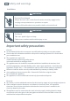
2 Safety and warnings Installation WARNING! Electrical Shock Hazard Always disconnect the cooker from the mains electricity supply before carrying out any maintenance operations or repairs. Failure to follow this advice may result in death or electrical shock. WARNING! Cut Hazard Take care - panel edges are sharp. Failure to use caution could result in injury or cuts. Important safety precautions General To avoid hazard, follow these instructions carefully before installing or using this product.
Safety and warnings 3 A suitable disconnection switch must be incorporated in the permanent wiring, mounted and positioned to comply with the local wiring rules and regulations. The switch must be of an approved type installed in the fixed wiring and provide a 3 mm air gap contact separation in all poles in accordance with the local wiring rules. In Australia and New Zealand, a switch of the approved type with a 3 mm air gap must be installed in the active (phase) conductor of the fixed wiring.
4 Safety and warnings Operation Your freestanding cooker has been carefully designed to operate safely during normal cooking procedures. Please keep the following guidelines in mind when you are using it: WARNING! Explosion Hazard Do not store flammable materials such as gasoline near the cooktop. Do not store flammable material in the ovens or in the drawers. Do not spray aerosols near the cooktop during use. Failure to follow this advice may result in death or serious injury.
Safety and warnings 5 Important safety precautions Isolating switch: make sure this cooker is connected to a circuit which incorporates an isolating switch providing full disconnection from the power supply. Household appliances are not intended to be played with by children. Children, or persons with a disability which limits their ability to use the appliance, should have a responsible person to instruct them in its use.
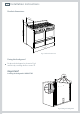
6 Installation instructions Product dimensions mm MAX 927 mm MIN 915 mm 120 mm 600 1195 mm Fig. 1 Product dimensions Fixing the backguard Position the backguard as shown in Fig. 2 and fix it by screwing the five screws “A”. Important! Installing the backguard is MANDATORY. A Fig.
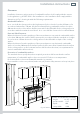
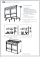
Installation instructions 7 Clearances Installation clearances and protection of combustible surfaces shall comply with the current local regulations eg. AS/NZS 5601.1 Gas Installations code. Installation shall comply with the dimensions in Fig. 3, bearing in mind the following requirements: Overhead Clearances In no case shall the clearance above the highest part of the cooker be less than 650 mm or, for an overhead exhaust fan, 750 mm.
8 Installation instructions Levelling the cooker Important! Fig. 4a 0 mm + 8 mm Fig. 4b Do not use the supplied nuts for height adjustments between 0 and 8 mm Using the supplied adjustable feet is MANDATORY. For safety reasons and to ensure adequate ventilation, the cooker chassis MUST NOT sit directly on the floor, a plinth, or other support surface. The cooker is already fitted with six levelling feet. Level the cooker by screwing or unscrewing the feet (Fig. 4d).
Installation instructions Fitting the anti-tilt bracket 9 Dotted line showing the position of the cooker when installed = = Important! To restrain the appliance and prevent it tipping accidentally, the antitilt bracket and restraining plate supplied must be fitted according to the instructions below. 1 Drill four 8mm diameter holes for the fixing screws (two in the wall and two in the floor-see Fig.5) and insert the plastic plugs supplied.
10 Installation instructions Moving the cooker Important! To prevent damaging the adjustable feet, ensure the cooker is always lifted by two people. Do not lift the cooker by the door handles. DO NOT DRAG the cooker. Lift the feet clear of the floor. Fig. 9a Correctly lifting the cooker Fig. 9b Incorrectly lifting the cooker Fig.
Installation instructions Locating the area for gas and electrical connection Dotted line showing the position of the cooker when installed Area for GAS and ELECTRCIAL connection Dimension Length (mm) ~ ~ Fig.
12 Installation instructions Connecting the cooker to the gas supply The gas connection must be carried out by an authorised person according to the relevant standards. Before connecting the appliance to the gas main, mount the brass conical adaptor onto the gas inlet extension pipe, upon which Back the washer has been placed (see Fig. 12 panel following). Conical adaptor and washer are supplied with Fig.
Installation instructions 13 Installation with a flexible hose assembly If this appliance has to be installed with a hose assembly, the installer shall refer to the network operator or gas supplier for confirmation of the gas type, if in doubt. When used with a flexible hose, the connector on the wall should be between 450 mm to 500 mm from the floor and 200 mm to 300 mm from the left-hand side of the appliance as viewed from the front. The hose connection on the appliance shall face downwards.
14 Installation instructions Converting to a different gas type This appliance is suitable for use with Natural gas or LPG (check the “gas type” sticker attached to the appliance). To convert from one gas type to another, you need to replace the injectors, and then adjust the minimum burning setting. See instructions on pages following.
Installation instructions Semi-rapid burner 15 Replacing the injectors Injector If the injectors are not supplied, contact your nearest Fisher & Paykel Authorised Service Centre. Fig. 14a Triple ring wok burner Injector To replace the injectors: 1 Remove the trivets and burners from the cooktop. 2 Using a spanner, remove the injectors (Figs.14a,14b,14c) and replace them with the ones according to the gas type (see the ‘Table for the choice of injectors’).
16 Installation instructions Adjusting the minimum burner setting Check whether the flame spreads to all burner ports when the burner is lit with the gas valve set to the minimum position. If some ports do not light, increase the minimum gas rate setting. Check whether the burner remains lit even when the gas valve is turned quickly from the maximum to the minimum position. If the burner does not remain lit, increase the minimum gas rate setting.
Installation instructions 17 Table for the choice of injectors Natural gas LPG 1.0 2.75 Test Point Pressure [kPa] Injector Orifice Dia. (mm) Gas Consumption [MJ/h] Injector Orifice Dia. (mm) Gas Consumption [MJ/h] Semi-rapid 1.12 6.30 0.70 6.30 Triple-ring wok 1.60 12.70 0.95 11.90 inner crown 0.85 (no.1 central) 3.60 (*) 0.50 (no.1 central) 3.20 (*) outer crowns 1.15 (no.2 outer) 16.00 (#) 0.62 (no.2 outer) 13.
18 Installation instructions Connecting the power supply cable 1 2 3 4 5 6 7 To connect the power supply cable to the cooker: Remove the four screws that hold shield “A” behind the cooker. Open the cable clamp “D” completely. Check the position of the U bolts on the terminal block “B” (Fig. 16a) corresponds to the connection diagrams in Fig. 16b and Fig. 16c. Insert the power supply cable into the cable clamp “D” and into the cable protector “C”.
TM V 8 9 10 11 8a 9a 10a 11a 1 2 3 4 5 T A V CF LF M S LF S CIR WD S1 CIR ELECTRIC DIAGRAM KEY F1 Oven switch F2 Warning drawer switch TE Oven thermostat LF Oven lamp PR Oven programmer S2 Pilot lamp S1 Thermostat pilot lamp TL Thermal overload TL1 Thermal overload M Terminal block C Top element G Grill element Bottom element S WD Warming drawer element A Ignition coil PA Ignition switces group CF Cooling fan V Fan T Earth connection S2 2 P2 TM G N/8 L/7 P1 PILOT 4 F2 C T
20 Introducing your cooker Thank you for buying a Fisher & Paykel freestanding cooker. Once it is installed and ready to use, you will want to know everything about it to make sure you get excellent results right from the start. This guide introduces you to all its special features. We recommend you read the whole guide before using your new cooker, for both safety and cooking success. For more information, go to www.fisherpaykel.com 11 7 10 8 9 18 1 2 3 15 17 4 5 6 14 16 12 13 Fig.
Using your gas cooktop 1 21 1 . 2 1 2 3 Semi-rapid burner Triple-ring wok burner Dual burner 3 3 2 Fig. 18 Cooktop layout Gas burners The knob controls the flow of gas through the safety valve. /OFF = closed valve = maximum flow = minimum flow You can choose to cook at any heat between and , but never between OFF. 0 Fig.
22 Using your gas cooktop Before using your cooktop Before using your new cooktop, please: Read this user guide, taking special note of the ‘Safety and warnings’ section. Switch the power to the cooker on at the wall. Make sure all burner control knobs are turned off. Using the gas burners (semi-rapid and triple-ring wok) 1 2 3 4 5 Choose the control knob for the burner you want to use. Press the knob down gently and turn it anticlockwise to the position. The ignitors on all the burners will spark.
Using your gas cooktop 23 To use the inner crown only, press down the control knob before turning it, then adjust the flame anywhere between and . Do not adjust the flame between and / OFF. To use the inner and outer crowns together, press down the control knob before turning it, then adjust the flame anywhere between and . 0 If a burner does not light Check that: The cooker is plugged in and the electricity is switched on. The gas is turned on.
24 Using your gas cooktop Matching cookware to burner Use flat-bottomed pans, and make sure that they match your burner, as shown in the following table. A small pot on a large burner is not efficient. Diameters of pans which may be used on the cooktop Burners Minimum Semi-rapid Dual Maximum 16 cm 24 cm with only inner crown operating 12 cm 24 cm with both inner and outer crowns operating 26 cm 28 cm 26 cm 28 cm Triple-ring wok Maximum diameter for wok pans: 36 cm Fig.
Cooktop troubleshooting Problem Possible solutions A burner does not light. Check that the power to the cooker is switched on at the wall. Check the gas supply valve is turned on and the supply to the house is working. You should hear the gas when you turn a burner on. Check the gas bottle is not empty. The ignitors may be dirty. Clean them with a toothbrush and methylated spirits. The burner parts may not be located properly. Check the assembly and make sure the burner cap is sitting flat.
26 Using your ovens for the first time Clock display Function knob 1 2 3 4 Temperature knob Control buttons Fig. 25 Control panel Before using your new oven, please: Read this user guide, taking special note of the ‘Safety and warnings’ section. Remove all accessories and packaging. Peel the protective film off all surfaces and accessories. Set the clocks. The ovens will not work until the clocks have been set. Condition the ovens: Put in the shelves and trays.
Oven controls and setting the clock 27 Buttons sets the timer sets the cooking time for automatic cooking sets the stop time for automatic cooking sets the clock, returns oven to manual mode, cancels automatic cooking decreases time and beep volume Fig. 27 Clock display and control buttons increases time Illuminated symbols If the display shows A U It means that... For more information flashing with 0.00 The clock needs to be set. See instructions below.
28 Cooking functions OVEN LAMP Only the oven light comes on. It remains on in all the cooking functions. BAKE The upper and lower heating elements come on. BAKE is the traditional method of cooking. It is best to cook on only one shelf at a time in this function. GRILL The grill at the top of the oven comes on. Preheat for five minutes. Use with the oven door closed and the temperature knob between 50 °C and 225 °C max. Do not grill for longer than 30 minutes at any one time.
Cooking functions 29 FAN BAKE The upper and lower heating elements and the fan come on. Important! Safe food handling: leave food in the oven for as short a time as possible before and after cooking or defrosting. This is to avoid contamination by organisms which may cause food poisoning. Take particular care during warmer weather. Notes on baking and roasting: Only use the fat filter for roasting. Remove before baking. Always clean the filter after cooking. Preheat the oven before baking.
30 Using the electronic timer You can use the timer at any time, even when the oven is not in use. Important! The timer does NOT turn the oven off. To set the timer 1 2 Press . 0.00 will show and the symbol will start flashing. Press and to set the time you want (up to 23 hours and 59 minutes, in 1-minute steps). After a few seconds, the clock will show the time of day with the symbol steadily lit. The timer is now counting down. To check the remaining time Press . To cancel the timer 1 2 Press .
Automatic cooking 31 To set the oven for automatic cooking 1 Set the oven: Check the clock shows the correct time (eg 12:07). Select the function and set the temperature. The oven will turn on. 2 Set the cooking time: Decide how long the food will take to cook, allowing time for preheating if necessary (eg 40 minutes). Press . Use and to set the cooking time. AUTO will show in the display. Set the stop time: Decide when you want your food to be ready by (eg 13:30). Press . Use and to set the stop time.
32 Using your warmer drawer The warmer drawer is on the left-hand side. You can heat it from 30 OC to 120 OC. It also has a moisture control selector. Before using your warmer drawer, please: Condition it by heating it on maximum for about two hours. Once cooled, wipe it out with a damp cloth and mild detergent, and dry thoroughly. Important! Only use the warmer drawer for keeping hot food warm.
Care and cleaning Important! Before you start cleaning your cooker, please: Read these cleaning instructions and the ‘Safety and warnings’ section at the start of this user guide. Turn the power to the cooker off at the wall. Make sure the cooker is a safe temperature to touch. Do not use a steam cleaner. Do not keep flammable substances in the ovens or drawers. General advice Wipe down the cooktop and wipe out the ovens after every use. Wipe up spills.
34 Care and cleaning Cleaning the burner parts and trivets You can remove and clean these parts with hot soapy water or non-abrasive detergents. Clean spills regularly before they become burnt on. Do not wash these parts in a dishwasher. After cleaning, check that the burners and their flame spreaders are dry before replacing correctly. It is very important to check that the burner flame spreader and the cap have been correctly positioned. Failure to do so can cause serious problems.
Care and cleaning Replacing the triple-ring wok burner Fit the burner ring to the housing as shown by the arrow in the Fig. following. Make sure the burner is not able to rotate (Fig.36). Probe Ignitor Cap Ring Fig. 36 Correct positioning of cap and ring - triple-ring wok burner Fig.
36 Care and cleaning Replacing the dual burners Ensure that you replace the dual burner correctly; the burner rib must be fitted as shown by the arrows in Fig.38a. Position the small central cap in its housing as shown by the arrows in Fig.38b. Position the big cap in its housing as shown by the arrows in Fig.38c. Fig. 38a Fitting the burner rib Important! Never unscrew the burner screws. Cleaning the cast-iron griddle Leave the griddle to soak before cleaning.
Care and cleaning 37 Cleaning the inside of your ovens Do not use abrasive cleaners, cloths or pads to clean the enamel. If you have purchased and installed catalytic panels, do not use any oven cleaners, abrasive cleaners, ammonia-based cleaners, products containing acids or alkalis or detergents on them. Fixing screw Fig.39 Removing the side racks (and catalytic panels if installed) To make cleaning easier, you can remove the side racks, the oven door, and the fat filter.
38 Care and cleaning Cleaning the enamel cavity Do not use abrasive cleaners, cloths or pads to clean the enamel. Clean the enamel on the inside of an oven when it has cooled down, using household detergents or an ammonia-based cleaner. You may use ‘off the shelf’ oven cleaners, if you carefully follow the manufacturers’ instructions. Caring for the catalytic panels The catalytic panels are not supplied with the cooker, but purchased and installed optionally.
Care and cleaning 39 Sliding shelf supports The telescopic sliding shelf supports make it safer and easier to insert and remove the oven shelves and trays. They stop when they are pulled out to the maximum position. Wipe the supports with a damp cloth and a mild detergent only. Do not wash them in the dishwasher, immerse them in soapy water, or use oven cleaner on them. 1 2 3 4 1 2 To remove the sliding shelf supports: Remove the side racks by unscrewing the fixing screws (Fig. 39).
40 Care and cleaning Cleaning the oven door glass Do not use harsh abrasive cleaners or sharp metal scrapers to clean the oven door glass since they scratch the surface, which may result in shattering of the glass. Removing the inner and middle panes of glass Fig.44a The oven door has three panes of glass. To clean these, you need to remove the inner and middle panes. 1 Lock the door open: Fully open the oven door (Fig. 44a). Fully open the lever “A” on the left and right hinges (Fig. 44b).
Care and cleaning 3 Remove the middle pane: Gently unlock the middle pane of glass from the bottom clamps by moving it as in Fig. 45b. Gently lift the bottom edge of the pane (arrow 1 in Fig. 45c) and remove it by pulling it out from the top clamps (arrow 2 in Fig. 45c). Clean the glass with an appropriate cleaner. Dry thoroughly, and place on a soft surface. 4 Now you can also clean the inside of the outer glass. 41 Fig.45a Fig.45b 1 2 Fig.
42 Care and cleaning Replacing the middle and inner panes of glass 1 2 Make sure the door is locked open (see Figs. 44a - 44c). M Replace the middle pane: Check that the four rubber pads are in place (“M” in Fig. 46a). Check that you are holding the pane the correct way. You should be able to read the wording on it as it faces you. Gently insert the top edge of the pane into the top clamps (arrow 1 in Fig. 46b), then lower the pane and insert the bottom edge into the bottom clamps (arrow 2 in Fig.
Care and cleaning 3 4 Replace the inner pane: Check that the four rubber pads are in place (“D” in Fig. 47a). Check that you are holding the pane the correct way. You should be able to read the wording on it as it faces you. Insert the pane in the left “E” and right “F” slide guides, and gently slide it to the retainers “H” (Fig. 47c). Replace the seal “G” by hooking in the three fixing hooks. Make sure that you put it in the correct way (Fig. 47e).
44 Care and cleaning Removing the oven door(s) 1 2 3 4 5 6 The oven door(s) can easily be removed as follows: Open the door to its full extent (Fig. 48a). Open the lever “A” completely on the left and right hinges (Fig. 48b). Hold the door (Fg. 48c). Gently close the door until left and right hinge levers “A” are hooked to part “B” of the door (Fig. 48d). Withdraw the hinge hooks from their location following arrow “C” (Fig. 48e). Rest the door on a soft surface. Fig.
Care and cleaning 45 Removing the drawers 1 2 3 Open the drawer completely (Fig. 49a). To disengage the drawer from the guide rails, press the lever of the left guide rail down and pull the lever of the right guide rail up. Remove the drawer, while still holding the levers. Important! Warming drawer (left drawer only): Do not remove drawer while hot or during operation. Be sure drawer is empty before removing. 3 Fig.49a Removing the drawers Replacing the drawers 1 2 Fig.
46 Care and cleaning Replacing the oven lamp 1 2 3 4 5 Switch the power to the cooker off at the wall. Let the oven cavity and the heating elements cool down. Remove the protective cover “C”. Unscrew and replace the bulb “B” with a new one suitable for high temperatures (300°C), with the following specifications: 230-240V, 50Hz, E14 and same wattage as the bulb being replaced (check wattage stamped on the bulb). Refit the protective cover “C”. Note: oven bulb replacement is not covered by your warranty.
Warranty and service 47 Before you call for service or assistance ... Check the things you can do yourself. Refer to the installation instructions and your user guide and check that: 1 2 Your product is correctly installed. You are familiar with its normal operation. If after checking these points you still need assistance, please refer to the Service & Warranty book for warranty details and your nearest Authorised Service Centre, or contact us through our website: www.fisherpaykel.
FISHERPAYKEL.COM © Fisher & Paykel Appliances 2018. All rights reserved. The product specifications in this booklet apply to the specific products and models described at the date of issue. Under our policy of continuous product improvement, these specifications may change at any time. You should therefore check with your Dealer to ensure this booklet correctly describes the product currently available. NZ AU 599941F / 1105645- ß1 02.