CLASSIC RANGEHOOD HC90PCTX1, HC90PCB1, HC90PCW1 and HC90PCR1 models INSTALLATION GUIDE NZ AU
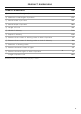
CONTENTS Safety and warnings 4 Parts supplied 6 Prior to installation 7 Product dimensions 8 Installation height 10 Attachment dimensions 11 Venting options 12 Prepare rangehood 15 Hang rangehood 17 Parts and accessories Final checklist 19 20 READ AND SAVE THESE INSTRUCTIONS The models shown in this installation guide may not be available in all markets and are subject to change at any time.
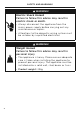
SAFETY AND WARNINGS ! WARNING! Electric Shock Hazard Failure to follow this advice may result in electric shock or death. • Always disconnect the appliance from the mains power supply before carrying out any maintenance or repairs. • Alterations to the domestic wiring system must be untaken by a qualified electrician. ! WARNING! Weight Hazard Failure to follow this advice may result in personal injury • The appliance is heavy.
SAFETY AND WARNINGS WARNING! When using this appliance always exercise basic safety precautions including the following: z Please read the entire set of instructions before installing or using this appliance. z Please make this information available to the person installing the appliance – doing so could reduce your installation costs. z Always switch the power off prior to installation, servicing or cleaning of the appliance.
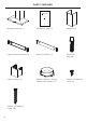
PARTS SUPPLIED CLASSIC RANGEHOOD HC90PCTX1, HC90PCB1, HC90PCW1 and HC90PCR1 models INSTALLATION GUIDE NZ AU Rangehood hood (1) Installation guide (1) Chimney (1) Upper chimney bracket (1) Chimney bracket (1) Expansion plug (10) Upper chimney (1) 150 mm diameter ducting adapter with damper (1) 10 mm self-tapping screw (4) 30 mm self-tapping screw (10) 6
PRIOR TO INSTALLATION Fisher & Paykel is not liable for any damage caused by not following these instructions. z z z z z z z z z Please read the instructions carefully. Unpack the rangehood. Ensure the voltage (V) and the frequency (Hz) indicated on the rating plate match the voltage and frequency of the installation site. Check all functions are working. Check that the area behind the installation surface to be drilled is clear of any electrical cables or pipes etc.
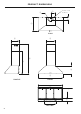
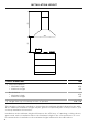
PRODUCT DIMENSIONS i j Power cord location h d PLAN g f A b e c PROFILE FRONT l k BOTTOM 8
PRODUCT DIMENSIONS PRODUCT DIMENSIONS MM A Maximum overall height of product 975 B Minimum overall height of product 636 C Overall width of product 898 D Overall depth of product 500 E Height of hood 298 F Width of chimney 320 G Depth of chimney 290 H Distance from centre of ducting outlet to back of product 95 I Distance from centre of ducting outlet to side of chimney 160 J Diameter of ducting outlet 150 K Distance between centre of lights 413 L Distance between lights to back of p
INSTALLATION HEIGHT A B HEIGHT DIMENSIONS MM A Ducted installation z Minimum height z Maximum height 636 Recirculation z Minimum height z Maximum height 676 B Height from top of cooktop to base of product 975 975 650 – 750 This rangehood must be installed no lower than the minimum height indicated in the table above. Minimum installation height may be greater if required by the cooktop, refer to your cooktop installation instructions.
ATTACHMENT DIMENSIONS H G Upper chimney bracket attachment points E Chimney bracket attachment points C F Upper rangehood hood attachment points D Lower rangehood attachment points B A ATTACHMENT DIMENSIONS MM A Lower rangehood attachment point width 508 B Lower rangehood attachment point height 47 C Upper rangehood attachment point width 250 D Upper rangehood attachment point height 294 E Chimney bracket attachment point width 250 F Chimney bracket attachment point height 596 G Uppe
VENTING OPTIONS Attention should be given to ensure that any applicable regulations concerning the discharge of exhaust air are fulfilled. The rangehood can be installed to operate with the exhaust air ducted externally from the kitchen, or installed to operate with the exhaust air recirculating within the kitchen. Ducted For ducted installation it is recommended that 150 mm diameter, rigid or semi-rigid ducting is used. This will require a 160 mm (min) round hole in the ceiling or wall.
VENTING OPTIONS Recirculating To enable the product to operate with the air recirculating, please purchase a recirculation diverter and carbon filters (refer to the ‘Parts and accessories’ section). This recirculation diverter is installed after a short length of ducting and is required to channel the air out the side vents at the top of the chimney. The carbon filters are required to remove odours.
ELECTRICIAL REQUIREMENTS Rating plate location Before connecting the rangehood to the power supply, ensure the voltage and frequency indicated on the rating plate match that of the installation location: MODEL HC90 14 FREQUENCY VOLTAGE 50 Hz 230 V
PREPARE RANGEHOOD Warning: Failure to install the screws or fixing device in accordance with these instructions may result in an electrical hazards. 1 Place the ducting adapter onto the rangehood and screw it into place using 10mm screws. 2 Remove the filters – pull the catch and tilt the filter downwards until it disengages from the supports.
ATTACH BRACKETS AND MOUNTING SCREWS 1 Temporarily mark the height of the bottom of the rangehood and the centre of the cooktop on the wall according to the information provided in 'Installation Height'. 2 Attach the chimney bracket and upper chimney bracket (if using the upper chimney). Use the 30mm screws and expansion plugs if attaching to masonry. Attach the upper hood mounting screws. Use the 30mm screws and expansion plugs if attaching to masonry.
HANG RANGEHOOD 1 2 Hang the rangehood off the upper rangehood mounting screws. Hang off the keyhole attachment points on the back of the rangehood then tighten the screws. Attach the lower rangehood mounting screws to fix the rangehood to the wall. Refit the filters. 3 Attach ducting to the ducting adapter using aluminium duct tape.
ATTACH CHIMNEY 1 Bend the tabs on the chimney. Rear view 2 Place chimney around the rangehood chassis and hang off the chimney bracket. 3 Extend the upper chimney and attach to the upper chimney bracket with 10mm screws.
PARTS AND ACCESSORIES ITEM REFERENCE NUMBER Semi rigid ducting kit 150 mm (eaves) PD-RHK150E Semi rigid ducting kit 150 mm (wall) PD-RHK150W Recirculation carbon filter x2 792481 Recirculation diverter 792560 19
FINAL CHECKLIST TO BE COMPLETED BY THE INSTALLER Rangehood is correctly installed All connections are secure Connections have not pierced any electrical or water lines within the wall Ducting has not been crushed or bent in any area's Flexible ducting has been pulled taut and any excess removed (if required) Power plug switch is accessible to the customer Product is plugged in and power switched on Operation of the product has been tested Complete and keep for safe reference: Model Serial no.
FISHERPAYKEL.COM © Fisher & Paykel Appliances 2020. All rights reserved. The product specifications in this document apply to the specific products and models described at the date of issue. Under our policy of continuous product improvement, these specifications may change at any time. You should therefore check with your Dealer to ensure this document correctly describes the product currently available. NZ AU 105939B 02.