Installation instructions and User guide Gas-on-glass cooktops CG604 and CG755 models GB IE
Contents Safety and warnings Installation instructions Introduction Using your cooktop Care and cleaning Troubleshooting Warranty and service Important! SAVE THESE INSTRUCTIONS The models shown in this manual may not be available in all markets and are subject to change at any time. For current details about model and specification availability in your country, please visit our local website listed on the back cover or contact your local Fisher & Paykel dealer.
2 Safety and warnings WARNING! Cut Hazard Beware of sharp edges when handling stainless steel appliances. Failure to use caution could result in injury or cuts. WARNING! Electrical Shock Hazard Before carrying out any work on the electrical section of the appliance, it must be disconnected from the mains power supply. Connection to a good earth wiring system is essential and mandatory. Failure to follow this advice may result in death or electrical shock.
Safety and warnings 3 Particular attention shall be given to the relevant requirements regarding ventilation. This product should not be sealed into the bench with silicone or glue. Doing so will make future servicing difficult. Fisher & Paykel will not be liable for costs associated with releasing such a product, nor for repairing damage that may be incurred in doing this. No combustible material or products should be placed on this product at any time.
4 Safety and warnings WARNING! Hot Surface Hazard This appliance becomes hot during use. Do not touch the cooktop components, burners, trivets/pan supports or the base when hot. Before cleaning, turn the burners off and make sure the whole cooktop is cool. Failure to follow this advice may result in serious injury. WARNING! Explosion Hazard Do not store flammable materials such as gasoline near the cooktop.Do not spray aerosols near the cooktop during use.
Safety and warnings 5 Important safety precautions Operation Children, or persons with a disability which limits their ability to use the appliance, should have a responsible person to instruct them in its use. The instructor should be satisfied that they can use the appliance without danger to themselves or their surroundings. If the power supply cable is damaged, it must only be replaced by an authorised person. Ensure that the electrical connection plug is accessible after installation.
6 Installation instructions Cooktop and cutout dimensions CG755: Electrical connection is made at the left rear C Gas connection is made at the right rear A B D CG604: Electrical connection is made at the right rear E G F Cooktop and cutout dimensions (mm) CG604 CG755 A B C D E F G overall width of cooktop 600 750 overall depth of cooktop 510 510 54 54 width of chassis 550 670 depth of chassis 467 467 overall width of cutout 560 680 overall depth of cutout 480 480 height o
Installation instructions 7 Clearances A E B C D B C D E minimum clearance from rear edge of cutout to: nearest combustible surface minimum clearance from glass surface to: rangehood minimum clearance from side edges of cutout to: nearest combustible surface minimum clearance below top of benchtop to: combustible surface nearest non-combustible surface (eg thermal protection barrier) minimum clearance from benchtop to: overhead cabinet not directly above the cooktop CG755 A CG604 Clearances (mm)
8 Installation instructions The appliance may be installed in a suitable room in accordance with the current laws in force. The appliance is designed and approved for domestic use only and should not be installed in a commercial, semi-commercial or communal environment. Installing the appliance in any of the above environments will void the warranty and could affect any third-party or public liability insurances you may have. The appliance must be installed in compliance with regulations in force.
Installation instructions 9 Ventilation requirements (all countries except UK) H min 650 mm Providing adequate ventilation The installer must refer to the current local regulations. Extractor hood to The room accommodating the gas cooktop must have extract steam adequate natural draught to allow combustion of the gas. The flow of air must come directly from one or more air vents made in the outside walls with a free area of at least 100 cm2.
10 Installation instructions Ventilation requirements (United Kingdom only) The appliance should be installed in a room or space with an air supply in accordance with BS 5440:2 2000. For rooms with a volume of less than 5 m3, permanent ventilation through a free area of at least 100 cm2 will be required.
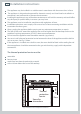
Installation instructions 11 Fastening the cooktop to the bench Note: if your bench is thicker than 40 mm, recess the underside to between 30 and 40 mm. S R R REAR S SF S F FRONT Seal Adhesive side Fig. 3 Preparing the cooktop before installation A S min R 30 mm A Fig. 4 Fastening the cooktop to the bench S F 40 mm FRONT CLAMPS 30 mm REAR CLAMPS min 5 30 mm 4 30 mm 3 Turn the cooktop upside down and place it on a soft surface.
12 Installation instructions Gas installation requirements This appliance is adjusted at the factory for use on Natural gas. To use it on LPG, it will first have to be converted. If the LPG conversion kit is not supplied with the appliance, contact your nearest Authorised Service Centre.
Installation instructions 13 Connecting the cooktop to the gas supply The gas connection fitting (Fig. 5) is made up of: the floating nut the elbow the washer. If using a flexible hose, make sure it does not come into contact with moving parts. To maintain the minimum 30 mm clearance requirement below the base of the cooktop, the rear of the chassis is recessed to provide a channel for the appliance inlet pipe.
14 Installation instructions When connecting the cooktop to the gas supply with rigid pipes or a flexible hose (which must comply with BS 669 in the UK), make sure that: you use rigid pipes or a flexible hose compliant with applicable local regulations.
Installation instructions 15 Leak-testing and flame-testing the cooktop 1 After connecting the gas supply, check the piping and connections for leaks as required by local regulations. The presence of bubbles indicates a leak. Tighten or replace connections as appropriate, then re-check for leaks. Important! Do not use any naked flame to check for leaks. 2 3 4 5 The operation of the appliance MUST be tested before leaving. Turn on the gas and light each burner.
IE Gas type: G30/G31 Gas type: G20 GB REDUCED POWER (HS - kW) NOMINAL POWER (HS - kW) 1,00 1,75 3,00 3,50 Auxiliary (A) Semi-rapid (SR) Rapid (R) Triple ring (TR) BURNERS 1,50 3,50 Triple ring (TR) 0,45 1,50 0,75 0,45 0,30 0,75 1,75 3,00 Rapid (R) 0,30 REDUCED POWER (HS - kW) Semi-rapid (SR) 1,00 NOMINAL POWER (HS - kW) Auxiliary (A) BURNERS Table for the choice of injectors 95 85 65 50 Ø INJECTOR (1/100 mm) 135 (T) 115 (Y) 97 (Z) 72 (X) Ø INJECTOR (1/100 mm) Cat: II
Installation instructions 17 Converting the cooktop to a different gas type Important! Only a suitably qualified and registered person may convert the cooktop to a different gas type. To convert from one gas type to another, you need to replace the injectors, and then adjust the minimum gas rate setting. 1 2 Replacing the injectors Remove the pan supports and burners from the cooktop.
18 Installation instructions Electrical connection Important! This appliance must be earthed. Installation must be carried out according to the manufacturer’s instructions. Incorrect installation may cause harm and damage to people, animals or property, for which the manufacturer accepts no responsibility. If the installation requires alterations to the domestic wiring system, call a qualified electrician.
Installation instructions 19 For the United Kingdom and the Republic of Ireland only: The appliance must be connected to a 220-240V~50 Hz supply by means of a suitably earthed three-pin socket and should be protected by a 3A fuse in the plug. If the appliance is supplied without a plug, fit a rewireable 13A three-pin plug fitted with a 3A fuse. Should the fuse require replacement, it must be replaced with a fuse rated at 3A and complying with BS1362.
20 Installation instructions Final checklist TO BE COMPLETED BY THE INSTALLER Have you installed the clamps? Have you clamped the cooktop to the bench securely? Have you used the supplied washers? Have you leak-tested all connections? Is the cooktop set for the correct gas type and pressure? Are the injector sizes correct for the gas type? Is the cooktop earthed? Check that the power supply cable is NOT touching the cooktop.
21
22 Introduction About your new cooktop Thank you for buying a Fisher & Paykel gas cooktop. Once it is installed and ready to use, you will want to know everything about it to make sure you get excellent results right from the start. This guide introduces you to all its special features. We recommend you read the whole guide before using your new cooktop, for both safety and cooking success. For more information, visit our local website listed on the back cover.
Using your cooktop 23 Gas burners The knob (Fig. 13) controls the flow of gas through the safety valve. Never cook or leave the knob between maximum and O (off ). OFF (closed valve) Maximum Minimum You can choose to cook at any heat between minimum and maximum Fig.13 Burner knob 1 Using the burners 1 2 3 4 Choose the knob for the burner you want to use. Press the knob down gently and turn it anticlockwise to the maximum position. The ignitors on all the burners will spark.
24 Using your cooktop If a burner does not light Check that: the cooktop is plugged in and the electricity is switched on the gas is turned on the gas bottle is not empty (if you are using bottled gas) you have held down the knob for at least 10 seconds the ignitors are sparking. If the ignitors are not sparking, they may be dirty or wet. Clean them with a toothbrush and methylated spirits, as shown in Fig. 15. Flame failure probe Ignitor Fig.
Using your cooktop 25 Matching cookware to burner Use flat-bottomed pans, and make sure they match the size of the burner, as shown in the following table. A small pot on a large burner is not efficient. Diameters of pans which may be used on the cooktop Burners Minimum Maximum Auxiliary 12 cm 14 cm Semi-rapid 16 cm 20cm*, 24 cm Rapid 24 cm 26 cm Triple-ring wok (five-burner models only) 26 cm 28 cm Maximum diameter for woks 36 cm * Front semi-rapid burner on four burner models only Fig.
26 Care and cleaning Important! Before any cleaning or maintenance, make sure that: all the burners are turned off the cooktop is disconnected from the power supply all parts of the cooktop are cool enough to safely touch. Important! For safety reasons, never unscrew the burner plate fixing screws. The burner plates can only be removed by an authorised service agent. Fig.
Care and cleaning 27 Cleaning chart What? Soiling examples Stainless steel strip fingerprints food stains How? 1 Wipe with a clean damp cloth. 2 Dry with a soft, lintfree cloth. Regular use of a stainless steel polish will reduce fingerprints and other marks Follow the manufacturer’s instructions. Important! Never use harsh/abrasive cleaning agents and scourers as they will damage the stainless steel finish.
28 Care and cleaning Replacing the auxiliary, semi-rapid, and rapid burners and pan supports Ensure that the burner and pan support assembly is: unable to rotate stable and level correctly aligned. Pan support Use the correct pan support only Cap Flame spreader Ignitor Flame failure probe Fig.
Care and cleaning 29 Replacing the triple-ring wok burner and pan support (five-burner models only) Ensure that the burner and pan support assembly is: unable to rotate stable and level correctly aligned. Flame spreader Ignitor Use the correct pan support only Flame failure probe Cap Ring Fig.
30 Troubleshooting Problem Possible solutions A burner does not light Check the cooktop is plugged in and the electricity is switched on. Check the gas supply valve is turned on and the supply to the house is working. You should hear the gas when you turn a burner on. If you use bottled gas, check the gas bottle is not empty. The ignitors may be dirty. Clean them with a toothbrush and methylated spirits. The burner parts may not be located properly.
Warranty and service 31 Before you call for service or assistance ... Check the things you can do yourself. Refer to the installation instructions and your user guide and check that: 1 2 your product is correctly installed you are familiar with its normal operation. If after checking these points you still need assistance, please refer to the Service & Warranty book for warranty and after-sales service details or contact us through our local website listed on the back cover.
34 Copyright © Fisher & Paykel 2008. All rights reserved. The product specifications in this booklet apply to the specific products and models described at the date of issue. Under our policy of continuous product improvement, these specifications may change at any time. You should therefore check with your Dealer to ensure this booklet correctly describes the product currently available. www.fisherpaykel.co.uk www.fisherpaykel.