CM6200 Starter System Installation Manual MODEL: RF-2W900FM-5PT Firstech, LLC. 21911 68th Ave S. Kent, WA 98032 Phone. 888-820-3690 Fax. 206-957-3330 Please visit www.firstechonline.
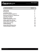
Starter System CM6200 Install Guide Table of Contents Introduction Kit Contents Installation Basics Remote Programming Routine Placement and Use of Components Common Procedures Wiring Descriptions Option Programming Tables Option Menu Descriptions Special Option Groups 1 & 2 Option Programming Troubleshooting Frequently Asked Questions Technical Support Contacts Copyright 2009 Firstech, LLC. www.firstechonline.com | www.compustar.
Starter System CM6200 Install Guide Copyright 2009 Firstech, LLC. www.firstechonline.com | www.compustar.
Starter System CM6200 Install Guide www.firstechonline.com | www.compustar.com Introduction CM6200 Thank you for purchasing this Firstech system for your vehicle. The following installation manual is intended for experienced and authorized Firstech technicians. We highly recommend that you contact your local Firstech dealer and seek professional installation. Call 888-820-3690 or visit our websites at www.compustar.com or www.firstechllc.com to locate your nearest dealer.
Starter System CM6200 Install Guide Installation Basics www.firstechonline.com | www.compustar.com CM6200 If you are new to installing Firstech Series Remote Starts and / or Alarms, we highly recommended that you thoroughly review this manual to installing your first unit. Key Points to Consider Before Installation: You must code remotes to this system before anything will function. Program remotes by cycling the ignition ON / OFF five times within 7 seconds and tap button 1 (0.
Starter System CM6200 Install Guide Remote Programming Routine www.firstechonline.com | www.compustar.com CM6200 IMPORTANT: Any and all remotes must be coded to the control module prior to performing any and all operations. Remotes excluding 2WSSR-Pro STEP 1: Activate programming mode by manually turning the vehicle’s key between the Ign On and Off (or the Acc & On positions) five times within 7 seconds. The vehicle’s parking lights will flash once with the successful completion of this step.
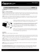
Starter System CM6200 Install Guide Placement and Use of Components www.firstechonline.com | www.compustar.com CM6200 IMPORTANT: The placement and use of components are critical to the performance of this system. Antenna and Cable Firstech antennas are calibrated for horizontal installation at the top of the windshield. The cable that connects the antenna to the control module must be free from any pinches or kinks.
Starter System CM6200 Install Guide Common Procedures www.firstechonline.com | www.compustar.com CM6200 Jumper Settings Caution: Jumper settings affect the polarity and use of certain outputs. If these jumpers are used incorrectly, damage to the vehicle and /or control module may occur. Jumper 1 (Door Trigger Polarity) Determines the polarity of the door trigger input wire (red/white). In the default position the door trigger registers negative (-) triggers.
Starter System CM6200 Install Guide www.firstechonline.com | www.compustar.com STEP 1: Start the vehicle with the key. Allow time for the engine to idle down. STEP 2: Test wire and make connection. At idle the tach wire should test between 1 to 4 Volts AC. As the vehicle RPM’s increase the voltage on the meter will also increase. Always solder tach connections. STEP 3: Learn tach. While the vehicle is at idle, hold the foot brake and press and hold the remote start button on the remote control for 2.
Starter System CM6200 Install Guide www.firstechonline.com | www.compustar.com Timed Crank Setting – Automatic Transmission Only Option 2-10 setting 4 provides a timed 1.5 second crank for the remote start sequence. This option just cranks the vehicle for 1.5 seconds and assumes remote start has completed. This option can be used for GM and other vehicles with built in anti-grind systems. Green/White Loop This loop wire determines the transmission setting.
Starter System CM6200 Install Guide www.firstechonline.com | www.compustar.com Additional Notes Reservation mode will be cancelled if the control module recognizes the vehicles door, hood or trunk opening – or if the alarm is triggered. Each time the end user wants to remote start their manual transmission vehicle, they must set the control module in reservation mode. Reservation mode settings can be programmed with Option 1-06.
Starter System CM6200 Install Guide Wiring Descriptions www.firstechonline.com | www.compustar.com CM6200 Connector 1 (CN1), 6-Pin Pin 1 White – Accessory 12V positive (+) output. This wire must be connected to the vehicle accessory / HVAC blower motor wire. The proper wire will test 0V with the key in the off position, (+) 12V while key is in the on position, 0V while cranking and back to (+) 12V when the key is returned to the on position. This wire has a 20 amp fuse on it.
Starter System CM6200 Install Guide www.firstechonline.com | www.compustar.com IMPORTANT: For anti-grind and starter-kill applications, the yellow wire goes to the starter side of the vehicles starter wire and the yellow/black goes to the key side. Pin 3 Green – Ignition 12V positive (+) output and input. This wire must be connected to the vehicles ignition for remote start and valet/programming.
Starter System CM6200 Install Guide www.firstechonline.com | www.compustar.com Connector 3 (CN2), 20-Pin: Programmable Output Connector (POC) IMPORTANT: Odd Pin numbers 1 through 17 are programmable for up to 12 different output types. Refer to Special Option Group 2 for details. Pin 1 Blue - 250mA negative (-) output when armed and during remote start (while running). This wire is pre-wired to the anti-grind/starter-kill relay.
Starter System CM6200 Install Guide www.firstechonline.com | www.compustar.com Pin 11 Black [POC 5] – Status/Ground while running 250mA negative (-) output. This is an optional output that will provide a negative (-) output before the ignition cranks and stay on throughout the remote start dura tion. This wire is most commonly used to trigger bypass / transponder modules. Pin 12 Brown/White - This is a dual-purpose wire that is selectable through Option 4-9 in the programming able.
Starter System CM6200 Install Guide www.firstechonline.com | www.compustar.com Pin 18 Gray/Black – Hood Pin negative (-) input. This input is a safety shut down and alarm trigger. It prevents the vehicle from remote starting while the hood is open and triggers the alarm if the hood is opened while the alarm is armed. You can connect this wire to the hood pin supplied with this kit, or to a wire in the vehicle that shows (-) only while the hood is open.
Starter System CM6200 Install Guide www.firstechonline.com | www.compustar.com Connector 5 (CN5), 4-Pin (RS 232 Data Port) This connector is used for updating control modules via www.firstechonline.com. You must also use this port to flash Blade bypass modules. This port provides simple connectivity of Fortin and iDataLink bypass modules. Connector 6 (CN6), 4-Pin D.A.S. Sensor Input For future use: This connector is designed for used with the Firstech D.A.S sensor.
Starter System www.firstechonline.com | www.compustar.com CM6200 Install Guide Connector 10 (CN10), 2-Pin (Pre-wired LED) Note: Do not mistake for Thermister port. Pin 1 Black - L.E.D negative (-) ground. Pin 2 Black/White- L.E.D. 3V positive (+) output. Connector 11 (CN11), 3-Pin (Pre-wired Valet/Programming Switch) Pin 1 Gray/Black - Negative (-) ground. Pin 2 Gray – 3V positive (+) L.E.D. output. Pin 3 Gray – Negative (-) output.
Starter System www.firstechonline.com | www.compustar.
Starter System www.firstechonline.com | www.compustar.
Starter System www.firstechonline.com | www.compustar.
Starter System CM6200 Install Guide www.firstechonline.com | www.compustar.com 1-04 Double Pulse Unlock - If enabled, this option will cause the system to double pulse the unlock output. This option is used on a majority of Toyota vehicles. The first unlock pulse disarms the alarm, and the second pulse unlocks the doors. 1-05 Rearm Output - These optional settings change the event trigger on the orange rearm wire. 1-06 Reservation Lock - Manual transmission only.
Starter System CM6200 Install Guide www.firstechonline.com | www.compustar.com 2-01 Tach Sensing Method – This option will adjust the method at which tach is read by the module. At de fault this option will minimize overcrank during remote start. 2-02 Turbo Mode – This option will adjust the run time after Turbo mode has been engaged. The e-brake and door trigger inputs must be connected and the option must be turned on through the remote for turbo timer to engage.
Starter System CM6200 Install Guide www.firstechonline.com | www.compustar.com 2-09 Temperature of Hot Starting – Works in conjunction with Options 2-05 and 2-06. See the option table for available temperatures. 2-10 Engine Sensing – Review the “Common Procedures” section for complete explanations on the four engine sensing modes. 2-11 Runtime Extension – This option resets the engine run countdown before the vehicle shuts off for either the remote start or turbo timer.
Starter System CM6200 Install Guide www.firstechonline.com | www.compustar.com 3-09 Horn Output When Alarm is Triggered - This changes the behavior of the white horn wire when the alarm is triggered. With this setting you can change the wire to a constant (-) negative output for an ad ditional siren. 3-10 Valet – This option changes valet modes. Default 1: Key on/off five times or remote valet (I + III for 0.5 seconds) with key in the on position.
Starter System CM6200 Install Guide www.firstechonline.com | www.compustar.com 4-05 Secure Aux Output – On the default setting, button 4 on the remote must be pressed first before Aux 1 or Aux 2 can be triggered. This prevents accidental triggering of the outputs. Option setting II turns this feature off. 4-06 Aux 1 Input – This option changes the input behavior of the pre-warn wire on the Aux Input Sensor green connector. Default 1: Will pre-warn with a negative (-) ground input.
Starter System CM6200 Install Guide www.firstechonline.com | www.compustar.com 4-13 Antenna Power Save - Some people may not drive their vehicle very often, this may cause the battery to become discharged because it is not getting recharged on a regular basis. The antenna power save option will turn off the antenna after the specified amount of time to conserve power. While the antenna is asleep, the system will not respond to the remotes.
Starter System CM6200 Install Guide www.firstechonline.com | www.compustar.com Option Programming CM6200 Option Programming Using the OP500 (programmer) The OP500 can be used to program any available option. It is required to program options in Special Option Groups 1 and 2. STEP 1: Using the blue connector on the top of the OP500, connect it to the control module via the antenna wire. (Use the included extension cable if necessary.
Starter System www.firstechonline.com | www.compustar.com CM6200 Install Guide Select Option 2 Select Option 3 Select Option 4 Tap Button 4 Tap Button 4 Tap Button 4 Tap Button 4 Select Option 1 (1 + 2) for 2.5 seconds then (1 + 2) for 2.5 seconds (1 + 2) for 2.5 seconds then (1 + 4) for 2.5 seconds (1 + 4) for 2.5 seconds then (1 + 2) for 2.5 seconds (1 + 4) for 2.5 seconds then (1 + 4) for 2.
Starter System CM6200 Install Guide www.firstechonline.com | www.compustar.com Troubleshooting CM6200 Remote Start Error Codes If the remote start fails to start the vehicle, the parking lights will flash two times immediately.
Starter System CM6200 Install Guide www.firstechonline.com | www.compustar.com Frequently Asked Questions CM6200 I have everything hooked up and the system will not respond. A: The remotes need to be programmed. Review the “Common Procedure” section of this manual. I am trying to program the control module with the OP500 Option Programmer and it flashes “ER 01” when I plug it in to the antenna cable. What should I do? A: Make sure that the system is not locked/armed.
Starter System CM6200 Install Guide www.firstechonline.com | www.compustar.com The vehicle starts and shuts down 3 times in a row. A: This usually means that the engine sensing mode is not working correctly. If you are using a coil, change to an injector or try alternator mode. The vehicle will lock and unlock, but will not remote start or flash the parking lights. A: The system is in valet mode. Tap buttons (I) + (III) for 0.5 seconds while the key is in the on position.
Starter System CM6200 Install Guide Technical Support Contacts www.firstechonline.com | www.compustar.com CM6200 Firstech technical support is reserved for authorized dealers only. Monday - Friday: 888-820-3690 (8:00 am – 5:00 pm Pacific Coast Time) Email: support@compustar.com Web: Register at: www.firstechonline.com click on “Authorized Tech” Wire Diagrams Click on the “Installogy Access Client” link found on your desktop.