PS1010-3A Multifunctional Digital DC power supply USER MANUAL • • • • • Voltage controllability Current controllability Digital voltmeter function High power efficiency Bright display IBBI Electronics 1
Table of Contents 1 2 3 4 5 Safety precautions...................................................3 Device overview .....................................................3 Getting started.........................................................3 Operating conditions...............................................4 Device operation .....................................................5 5.1 Setting output voltage .....................................5 5.2 Setting current limit ..................................
1 Safety precautions • • • Do not operate under Lightning conditions Do not keep in wet areas Always adjust required voltage/current, before connecting the power lines to the DUT 2 Device overview PS1010 is a PWM controlled highly power efficient digital power supply.
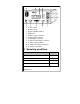
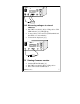
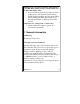
1 2 3 4 5 6 11 10 9 8 7 1. Power switch 2. Display-value 3. Display-unit/information 4. LED panel 5. Output voltage controller 6. Current limit controller 7. C-limit display selection 8. Voltage-Current display selection 9. Voltage out put terminal 10. Voltmeter-V/C display selection 11.
Voltmeter range 0-35V 5 Device operation 5.1 Setting output voltage • • • • • Put VM/Vout switch [(10)] to Vout position Put C/V switch [(8)] to V position Volt LED indicator will light up [(4)] [(3)] will display “U” for Volt Adjust the voltage controller [(5)] to get the required value. • The value will be displayed on [(2)] with one decimal place Note: Make sure to keep reasonable current limiting value before setting output voltage so that current control (CC) will not take over. 5.
• • • • • Put VM/Vout switch [(10)] to Vout position Put C/V switch [(8)] to C position Amp LED indicator will light up [(4)] [(3)] will display “A” for Ampere Actual current value will be displayed on [(2)] with two decimal places 5.4 Voltmeter mode 5.4.1 Measuring voltage at various positions while powered from the PS1010-3A • Set required output voltage and power up the DUT • Put VM/Vout switch [(10)] to VM position. VM LED indicator [(4)] will light up.
5.4.2 Measuring voltages at external sources • • • Put VM/Vout switch [(10)] to VM position. VM LED indicator [(4)] will light up Connect wires as shown below(VM terminal and the GND of Vout terminals) Value will be displayed [(2)]. 5.
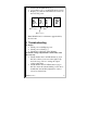
• • • Switch ON the PS1010-3A [(1)] [(3)] will show “F” to indicate Firmware version Display [(2)] will show the Firmware version in the following order. 6. 0. 1 Major version F Build Minor version Note: PS1010-3A is not firmware upgradeable by the customer. 6 Troubleshooting No display • Check power cable/Input power • Check power switch [(1)] • Check fuse at the back of the PS1010 Even if the voltage adjust knob is turned the value does not vary. • Check whether the Volt LED indicator [(4)] is ON.
PS1010 is in its current mode and the Amp indicator is also ON. But rotating current controller knob does not affect the display value. • You are at the current mode and at this mode the display shows only the actual current draw by the DUT. But rotating the current controller knob means changing the Max current limit. To see the max current limit, C-SET button should be pressed. Cannot increase voltage from a certain value. • Check whether CC indicator appears. If so, increase the current limit.
Contact details: IBBI Electronics, No185/B, Opatha, Kotugoda. Sri Lanka. Email: ibbi.electronics@gmail.com Tel/Fax: +94 11 229 6812 Web: http://ibbi.electronics.googlepages.