ViewBox 100 /802.
Copyright Copyright© ViewSonic Corporation, 2001. All right reserved. ViewSonic, the three birds logo, OnView, ViewMatch, and ViewMeter are registered trademarks of ViewSonic Corporation. Disclaimer: ViewSonic ® Corporation shall not be liable for technical or editorial errors or omissions contained herein; nor for incidental or consequential damages resulting from furnishing this material, or the performance or use this product.
AC PLUG CORD PRECAUTIONS FOR THE UNITED KINGDOM FOR YOUR SAFETY PLEASE READ THE FOLLOWING TEXT CAREFULLY IF THE FITTED MOULDED PLUG IS UNSUITABLE FOR THE SOCKET OUTLET THEN THE PLUG SHOULD BE CUT OFF AND DISPOSED OF SAFELY. THERE IS A DANGER OF SEVERE ELECTRICAL SHOCK IF THE CUT OFF PLUG IS INSERTED INTO AN APPROPRIATE SOCKET. If a new plug is to be fitted, please observe the wiring code as shown below. If in any doubt, please consult a qualified electrician. WARNING: THIS APPLIANCE MUSR BE EARTHEED.
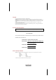
Table A Cord Type SJT SVT Size of Conductors In Cord 18AWG 16AWG 14AWG 18AWG 17AWG Maximum Current Rating of Unit 10Amps 12Amps 12Amps 10Amps 12Amps Important Safety Instructions Read these instructions carefully. Save these instructions for future reference. 1. Follow all warnings and instructions marked on the product. 2. Unplug this product from the wall outlet before cleaning. Do not use liquid cleaners or aerosol clears. Use a damp cloth for cleaning. 3. Do not use this product near water. 4.
Federal Communication Commission Interference Statement This equipment has been tested and found to comply with the limits for a Class B digital device, pursuant to Part 15 of the FCC Rules. These limits are designed to provide reasonable protection against harmful interference in a residential installation. This equipment generates, uses and can radiate radio frequency energy and, if not installed and used in accordance with the instructions, may cause harmful interference to radio communications.
Contents Chapter 1 7 Welcome to ViewBox 100!...................................... 7 Introducing ViewBox 100 .NET Client ................................................................7 Unpacking the System ........................................................................................8 Checking Accessories: .............................................................................8 Chapter 2 9 Getting Started ..................................................... 9 System Overview...........
Chapter1 Welcome to ViewMate! Chapter 1 Welcome to ViewBox 100! Introducing ViewBox 100 .NET Client Congratulations on your purchase of this ViewBox 100 product! This high quality system is based on a stand-alone Intelligent .NET Client. This system offers an easy way for you connecting to Internet anywhere. The ViewBox 100 also features the following innovative design features ? Compact Size: Uses less than one quarter the space of a conventional ? PC.
Chapter 1 Welcome to ViewMate! Unpacking the System When opening the box of the computer, make sure not to be damage the box, and you may save the original box and all packing material for future shipping needs. Upon unpacking the box, make sure the following components are included in the box and are in good condition. If you find that any of these components are missing or appear damaged, please contact the ViewSonic Corporation support.
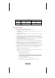
Chapter1 Getting Started Chapter 2 Getting Started System Overview Front Panel Figure 1-1. The front panel of ViewBox 100.NET Client Refer to the following illustrations to identify components located at the front panel of the ViewBox 100, as shown in Figure 1-1. 1. Power Button: Pressing this button enables you to power on/off the system. 2. Power On/Off Indicator: The indicator lights up when the system power is on.
Chapter 2 Getting Started 3. USB Port x 2: Two USB ports allow input and output devices to be easily attached to the ViewBox 100. Please plug in your USB devices in these two ports. 4. Line-out/Speaker Jack: This jack is connected to your audio device that receives the audio output of the system, such as speakers, or headphones. 5. Microphone Jack: This jack is connected to your microphone.
Chapter1 Getting Started Rear Panel Figure 1-2. The rear panel of ViewBox 100 The rear panel of the ViewBox 100 is where you connect power, peripheral devices such as a PS/2, input devices and output devices such as the display monitor. Please refer to the above figures for the location of each of the rear components, as shown in Figure 1-2. 1. Wall Line Jack (optional): (HPNA Configuration) This jack is connected to the phone line. 2.
Chapter 2 Getting Started 6. Monitor/VGA Connector (blue): Please connect this port with your monitor. 7. PS/2 Keyboard Connector (purple): Please plug in your PS/2 keyboard into this connector. 8. PS/2 Mouse connector (green): Please plug in your PS/2 mouse cable here. 9. Power Adapter jack: This jack is connected to the AC Adapter (provided). Connecting Your Peripheral Devices Connecting a Monitor Connect the monitor cable to the VGA connector on the rear panel of the ViewBox 100.
Chapter1 Getting Started Figure 1-4. Connecting a USB Keyboard via the USB connector Connecting a USB Mouse Plug the USB Mouse cable connector into the USB mouse connector on the USB Keyboard as shown in Figure 1-4 and Figure 1-5. Figure 1-5. Connecting a USB Mouse via USB Keyboard NOTE: There are two standard PS/2 keyboard and mouse connectors built-in on the rear panel of the ViewBox 100. You can also plug the standard PS/2 keyboard and mouse cable connectors into these connectors.
Chapter 2 Getting Started Connecting HPNA Cables (Optional) Connect the phone and wall lines to the HPNA (Home Personal Network Assistant) card connectors, as shown in Figure 1-6. Figure 1-6. Connecting the HPNA cables via Wall Line and Phone Jack Connecting Audio Cables ViewBox 100 has two integrated audio controller jacks (Line-out and Microphone jack) . You can connect a microphone to the microphone jack and a speaker or headphone to the Line-out jack, as shown in Figure 1-7. Figure 1-7.
Chapter1 Getting Started Connecting USB Devices If you have the USB devices, you can connect these to the USB connectors. To connect a USB device to the USB connector, plug the USB device cable connector into the USB connector of your ViewMate 100, as shown in Figure 1-8. Figure 1-8. Connecting USB devices via USB Connector Connecting the Network If you are under a LAN environment, you can connect to the network via the Ethernet connector to the Hub, as shown in Figure 1-9. Figure 1-9.
Chapter 2 Getting Started Connecting the Power Adapter Plug one end of the power adapter to the power adapter jack, and then the other end of the power cord into the wall outlet, as shown in Figure 1-10. Figure 1-10.
Chapter3 Other Information Chapter 3 Other Information Specification Dimension 225 (L) x 233.5(H) x 38 (W) mm (w/plastic) Chassis ? base Metal case ? Use 0.
Chapter 3 Other Information Front Panel LED spec. ? USB ? Audio Jack ? 1394 connector ? 2 ? 2 (for Headphone-out and MIC-in) ? No ? Power Button ? Yes ? Power LED ? LAN LED in connector ? Green Always on/off: Power on/off ? Upper: Green blinking for active. Lower: Orange for link. Power Supply ? Vendor ? Watts ? Hipro and Delta ? 12V/36W Wireless LAN ? AMBIT Certification ? Mini PCI 802.
Chapter3 Other Information Question: Solution: Screen display is small Question: Solution: No Sound ? Use a lower vertical refresh rate. If the refresh rate is too high, some monitors will compensate by making the image smaller. ? Be certain the power is on for the speakers. Make sure that the unit is hooked up to an AC adapter and the power button is ON. ? Use only the AC adapter provided. Check the connections between the computer and the speakers. ? Be certain there is output from the sound device.
Chapter 3 Other Information Customer Support For the most expedient answer to your question, do the following: 1. Check “Trouble Shooting” on the previous section. 2. For assistance contact your reseller. 3. For further assistance see the contact information listed below. If contact information for your country or region is not listed below, ask your reseller to refer you to a service center. NOTE: You will need to provide the serial number (on the back of the product).
Chapter3 Other Information Appendix Limited Warranty ViewBox 100 What the warranty covers: ® ViewSonic warrants its products to be free from defects in material and workmanship during the warranty period. If a product proves to be defective in material or workmanship during the warranty period, ViewSonic ® will at its sole option repair or replace the product with a like product. Replacement product or parts may include remanufactured parts or components.
Chapter 3 Other Information This warranty gives you specific legal rights, and you may also have other rights which vary from state to state. Some states do not allow limitations on implied warranties and/or do not allow the exclusion of incidental or consequential, so the above limitations and exclusions may not apply to you. Sales outside the U.S.A.: For ViewSonic products sold outside of the U.S.A., contact your ViewSonic dealer for warranty information and services.