
Operation Manual

9
Assembly Instructions
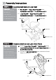
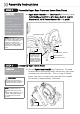
STEP 3
Assembly Upper Seat Frame and Lower Seat Frame
a) Upper Seat Frame[3] onto Mainframe[1] and secure using
1x M10x25mm Bolt[10],1x M10 Nyloc Nut[14], 2xM10
Washers[12], M10 Plastic Washer[13] and L-pin[6].
Note: Tighten the
M10x25mm Bolt, Washers
and Nylock until lightly snug
only. Over-tightening will
prevent the seat from
rotating. Use the L-pin to
tighten the Upper Seat
Frame once rotated into
place.
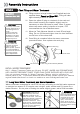
STEP 4
Assembly Right Crank Pedal
12
a) Secure Right Crank Pedal[8] onto Crank arm. The pedal
threads have a blue coating which will feel very tight when
threaded onto the crank arm. This is a type of thread
locker, and once in contact with the crank arm threads
will activate in approximately 15minutes.
2
REQUIRED
Right Crank Pedal [8]
CAUTION
Extreme over-tightening
could damage the aluminum
threads on the crank arm
Note: Allow 15 minutes
for the thread-locker to
activate before first time
use.
Check pedal tightness on a
regular basis and tighten
as needed with a 15mm
wrench.
Right Crank Pedal
M10x25mm Bolt
M10 Washer
Before installing
the Upper Seat
Frame onto the
Lower, use the
supplied grease
and apply liberally
between the two
sliding surfaces
L-Pin
M10 Plastic Washer
lubricating grease
M10 Nylock Nut
REQUIRED
Mainframe [1]
Upper Seat Frame [3]
L– Pin [6]
M10 x 25mm Blots [10]
2 x M10 Washers [12]
M10 Plastic Washers [13]
M10 Nyloc Nuts [14]