® Firepower FP 95 FLUX CORED WELDER Operating Manual A-13015 Révision : AB Issue Date: April 8, 2016 Manual No.: 0-5122 www.firepoweronline.
WE APPRECIATE YOUR BUSINESS! Congratulations on your new Firepower product. We are proud to have you as our customer and will strive to provide you with the best service and reliability in the industry. This product is backed by our extensive warranty and world-wide service network. To locate your nearest distributor or service agency, visit us on the web at www.firepoweronline.com. This Operating Manual has been designed to instruct you on the correct use and operation of your Firepower product.
! WARNING Read and understand this entire Manual and your employer’s safety practices before installing, operating, or servicing the equipment. While the information contained in this Manual represents the Manufacturer's best judgement, the Manufacturer assumes no liability for its use. Firepower FP 95 Flux Cored Welder Operating Manual Number 0-5122 Published by: ESAB Group, Inc. 2800 Airport Rd. Denton, TX 76208 www.firepoweronline.com Copyright 2015 by ESAB All rights reserved.
Be sure this information reaches the operator. You can get extra copies through your supplier. CAUTION These INSTRUCTIONS are for experienced operators. If you are not fully familiar with the principles of operation and safe practices for arc welding and cutting equipment, we urge you to read our booklet, “Precautions and Safe Practices for Arc Welding, Cutting, and Gouging,” Form 52-529. Do NOT permit untrained persons to install, operate, or maintain this equipment.
TABLE OF CONTENTS SECTION 1: SAFETY......................................................................................... 1-1 1.0 2.0 Safety Precautions........................................................................................... 1-1 Précautions de sécurité................................................................................... 1-3 SECTION 2: INTRODUCTION....................................................................................... 2-1 2.01 2.02 2.03 2.04 2.05 2.06 2.
TABLE OF CONTENTS APPENDIX 1: OPTIONS AND ACCESSORIES............................................................. A-1 APPENDIX 2: POWER SUPPLY REPLACEMENT PARTS................................................ A-2 APPENDIX 3: FIREPOWER FP 95 FC SYSTEM SCHEMATIC........................................... A-4 REVISION HISTORY.........................................................................................
SAFETY INSTRUCTIONS FIREPOWER FP 95 FC SECTION 1: SAFETY 1.0 Safety Precautions Users of ESAB welding and plasma cutting equipment have the ultimate responsibility for ensuring that anyone who works on or near the equipment observes all the relevant safety precautions. Safety precautions must meet the requirements that apply to this type of welding or plasma cutting equipment. The following recommendations should be observed in addition to the standard regulations that apply to the workplace.
FIREPOWER FP 95 FC WARNING SAFETY INSTRUCTIONS Arc welding and cutting can be injurious to yourself and others. Take precautions when welding and cutting. Ask for your employer's safety practices which should be based on manufacturers' hazard data. ELECTRIC SHOCK - Can kill. - Install and earth (ground) the welding or plasma cutting unit in accordance with applicable standards. - Do not touch live electrical parts or electrodes with bare skin, wet gloves or wet clothing.
SAFETY INSTRUCTIONS 2.0 FIREPOWER FP 95 FC Précautions de sécurité Les utilisateurs du matériel de soudage et de coupage plasma ESAB ont la responsabilité ultime d'assurer que toute personne qui opère ou qui se trouve dans l'aire de travail observe les précautions de sécurité pertinentes. Les précautions de sécurité doivent répondre aux exigences applicables à ce type de matériel de soudage ou de coupage plasma.
FIREPOWER FP 95 FC AVERTISSEMENT SAFETY INSTRUCTIONS LE SOUDAGE ET LE COUPAGE À L'ARC PEUVENT CAUSER DES BLESSURES À L'OPÉRATEUR OU LES AUTRES PERSONNES SE TROUVANT DANS L'AIRE DE TRAVAIL. ASSUREZ-VOUS DE PRENDRE TOUTES LES PRÉCAUTIONS NÉCESSAIRES LORS D'UNE OPÉRATION DE SOUDAGE OU DE COUPAGE. DEMANDEZ À VOTRE EMPLOYEUR UNE COPIE DES MESURES DE SÉCURITÉ QUI DOIVENT ÊTRE ÉLABORÉES À PARTIR DES DONNÉES DES RISQUE DU FABRICANT. CHOC ÉLECTRIQUE - peut être mortel.
INTRODUCTION FIREPOWER FP 95 FC SECTION 2: INTRODUCTION 2.01 How To Use This Manual 2.02 Equipment Identification This Owner’s Manual applies to just specification or part numbers listed on page i. To ensure safe operation, read the entire manual, including the chapter on safety instructions and warnings. Throughout this manual, the words WARNING, CAUTION, DANGER, and NOTE may appear. Pay particular attention to the information provided under these headings.
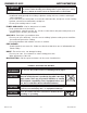
FIREPOWER FP 95 FC INTRODUCTION 2.05 Specifications Description Firepower FP 95 FC Package System Part Number 1444-0322 Power Source Weight 37.15 lb ( 16.8 kg) Power Source Dimensions HxWxD 14"x7"x15" (355.6 x 177.8 x 381mm) Number of Phases 1Ø Frequency 60Hz Flexible Supply Cable Size 7 ft (2.25 m) 14AWG Supply Lead Plug Type 5-15P Nominal Input Voltage 120V AC Rated Input Current 15A Rated kVA @ 100% Duty Cycle 1.
INTRODUCTION FIREPOWER FP 95 FC 2.06 Volt - Amp Curves FP-95 FIREPOWER 30 Vin=115V 60Hz Art # A-09068 28 26 24 22 OUTPUT VOLTAGE 20 18 16 14 12 10 8 6 4 2 0 0 5 10 15 20 25 30 35 40 45 50 55 60 OUTPUT CURRENT 65 70 75 80 85 90 95 100 Figure 2-1: Volt/Amp curves of the FirePower 95 2.07 Duty Cycle Duty Cycle is the amount of arc-on time (actual welding time) during any 10 minute period that a machine can operate at it’s rated output without damaging internal components.
FIREPOWER FP 95 FC INTRODUCTION This Page Intentionally Blank Manual 0-5122 2-4 Introduction
INSTALLATION FIREPOWER FP 95 FC SECTION 3: INSTALLATION 3.01 Location NOTE! The supply wiring for the welding power source must be capable of handling a minimum of 20 amperes. The welding power source must be the only load connected to the supply circuit. Poor unit performance or frequently opening line fuses or circuit breakers can result from an inadequate or improper supply.. For best operating characteristics and longest unit life, take care in selecting the installation site.
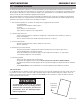
FIREPOWER FP 95 FC Spring Hub INSTALLATION 3.08 Install Wire into the Feedhead D-Ring WARNING ELECTRIC SHOCK CAN KILL! Make certain the machine is unplugged from the power receptacle. Do not plug machine in until told to do so in these instructions. Wire Spool Spool Locking Knob If Not Installed Load the Wire Spool per directions in section 3.06 onto the hub so that the wire will feed off the spool as the spool rotates counter- clockwise.
INSTALLATION FIREPOWER FP 95 FC NOTE! If there is too much pressure on the drive roll the wire gets locked and the motor could get damaged, If it is too loose the wire will not feed properly. Pressure Arm Pressure Adjust Device Art # A-09072_AB Figure 3-6: Wire Installed 3.09 Install Wire into the Welding Gun 1. Plug the Welding Power Source into the 120VAC receptacle.
FIREPOWER FP 95 FC INSTALLATION WARNING If ground connection clamp is in place on the workpiece the electrode wire is electrically “hot” when the gun switch is activated. 5. Activate the gun switch until the wire feeds out past the gun nozzle and deactivate the gun switch. Contact Tip Nozzle Wire Gun Switch Art # A-09074 Figure 3-9: Feed Wire Through Gun 6. Set the Voltage Power Switch to "OFF" and unplug the supply cord. 7. Replace the contact tip and nozzle.
OPERATION FIREPOWER FP 95 FC SECTION 4: OPERATION 4.01 General Safety Precautions Read and understand the safety instructions at the beginning of this manual prior to operating this machine. ! WARNING Be sure to put on proper protective clothing and eye safeguards (welding coat, apron, gloves, and welding helmet, with proper lenses installed). See Safety Instructions and Warnings chapter included in this manual. Neglect of these precautions may result in personal injury.
FIREPOWER FP 95 FC OPERATION Wire Speed Control On / Off Switch Hi / Low Powe Switch Ground Cable & Clamp MIG Welding Torch Wire Feeder Pressure Adjust Welding Wire Input Power Cable Art # A-09064_AD Figure 4-1: Firepower Controls Manual 0-5122 4-2 Operation
OPERATION FIREPOWER FP 95 FC 4.03 Flux Cored Arc Welding (FCAW) See Welding Guidelines included in this manual. 1. Make all necessary connections as instructed in the INSTALLATION chapter. 2. Place the WELDING OUTPUT VOLTAGE SELECTOR at the desired setting. 3. Rotate the WIRE SPEED FEED control to the desired setting. 4. Plug the supply cord into a 120 VAC 20 Ampere receptacle. 5. Connect the WORK CLAMP to the workpiece (material to be welded). 6.
FIREPOWER FP 95 FC OPERATION Flux-Cored Arc Welding (FCAW) This process also known as Open Arc, Innershield, FAB Shield, etc., is an electric arc welding process which fuses together the parts to be welded by heating them with an arc between a continuous flux filled electrode wire and the work. Shielding is obtained through decomposition of the flux within the tubular wire. The process is normally applied semi-automatically; however the process may be applied automatically or by machine.
OPERATION FIREPOWER FP 95 FC 4.08 Pre-Weld Procedure 1. Check the OPERATION chapter of this manual for details on this equipment. 2. Set the welding voltage range switch at position MIN or MAX. 3. Set the wire feed speed control to about the 2.5 setting. Readjust as necessary. 4. Review standard safe practice procedures in ventilation, eye and face protection, fire, compressed gas and preventative maintenance. See Safety Instructions and Warnings chapter included in this manual. 4.09 Welding Procedure 1.
FIREPOWER FP 95 FC OPERATION 4.11 Firepower FP 95 FC Welding Setting Selection Guide Material Type Wire Type Shielding Gas and Flow Rate Wire Size (Diameter) Steel Flux Core E71T-GS None Required .030" (0.8mm) .035" (0.9mm) Art # A-09033_AB THICKNESS L (MIN) Voltage Step Wire Speed H (MAX) 24 ga. 22 ga. (0.6mm) (0.7mm) L L 4 2 18 ga. 20 ga. (0.9mm) (1.2mm) L L 6 3 L L 7 3 16 ga. (3mm) 1/8" (3.
SERVICE FIREPOWER FP 95 FC SECTION 5: SERVICE 5.01 Cleaning of the Unit Periodically remove the right side panel (after disconnecting the supply cord from the receptacle) and blow out the interior with clean, dry, compressed air of not more than 25 PSI air pressure. Do not strike any components with the air hose nozzle. 5.02 Cleaning of the Feed Rolls Clean the wire groove on the feed roll at frequent intervals. This cleaning operation can be done by using a small wire brush.
FIREPOWER FP 95 FC SERVICE 5.04 Welding Problems FAULT 1 Undercut. 2 Lack of penetration. CAUSE REMEDY A Welding arc voltage too high. A Reduce voltage by reducing the voltage selection switch position or increase the wire feed speed. B Incorrect torch angle B Adjust angle C Excessive heat input C Increase the torch travel speed and/or reduce welding current by reducing the voltage selection switch position or reducing the wire feed speed.
SERVICE FIREPOWER FP 95 FC 5.05 Power Source Problems FAULT CAUSE REMEDY 1 Primary line voltage is ON. A Primary fuse is blown. Welding arc can not be established. B Broken connection in primary circuit. 2 Primary line voltage is ON but when the MIG Gun trigger switch is depressed nothing happens. A Replace primary fuse. B Have an Accredited ESAB Service Agent check primary circuit. MIG Gun trigger switch leads are disconnected. Reconnect.
FIREPOWER FP 95 FC SERVICE This Page Intentionally Blank Manual 0-5122 5-4 Service
Appendix A-1 Description Wire Feed Roll, Knurle, .023" - .030" /.035" (0.6-0.8mm/0.9mm), Hard/Cored Nozzle Contact Tip, .030" (0.8mm) Contact Tip, .035" (0.9mm) MIG Gun, Complete Assembly Part No. 1444-0427 1444-0050 1444-0026 1444-0027 1444-0741 Wire Feed Rolls & MIG Gun Consumables The branding size at the end of the feedroll refers to the size nearest to the mark. 0.8mm .030" E71T-GS Flux Cored Wire, .030" (0.8mm), 2 lbs (0.9kg) Spool E71T-GS Flux Cored Wire, .030" (0.8mm), 10 lbs (4.
FIREPOWER FP 95 FC APPENDIX APPENDIX 2: POWER SUPPLY REPLACEMENT PARTS ITEM DESCRIPTION PART NO. 1 CABLE CLAMP FOR CABLE DIAM.
APPENDIX FIREPOWER FP 95 FC 6 20 17 11 10 23 4 14 9 13 8 15 16 19 21 18 22 12 2 25 3 26 1 7 5 Art # A-09067_AD 24 Figure A-2: FP 95 FC Parts List Callouts Appendix A-3 Manual 0-5122
FIREPOWER FP 95 FC APPENDIX APPENDIX 3: FIREPOWER FP 95 FC SYSTEM SCHEMATIC Art # A-09025_AB Figure A-3: FP 95 FC Simple System Schematic Manual 0-5122 A-4 Appendix
APPENDIX FIREPOWER FP 95 FC This Page Intentionally Blank Appendix A-5 Manual 0-5122
FIREPOWER FP 95 FC APPENDIX Revision History Date Rev Description 03/19/2009 AA Manual release 04/08/2016 AB Rebrand updates, part number/art updates, schematic updates Manual 0-5122 A-6 Appendix
ESAB subsidiaries and representative offices Europe AUSTRIA ESAB Ges.m.b.H Vienna-Liesing Tel: +43 1 888 25 11 Fax: +43 1 888 25 11 85 BELGIUM S.A. ESAB N.V. Heist-op-den-Berg Tel: +32 70 233 075 Fax: +32 15 257 944 BULGARIA ESAB Kft Representative Office Sofia Tel/Fax: +359 2 974 42 88 THE CZECH REPUBLIC ESAB VAMBERK s.r.o.