
Installation Sheet

20
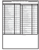
COUNTER PREPARATION
Consult Table 1 for non-combustible enclosure cut-out
dimensions. For Installation in non-combustible enclosures
only.
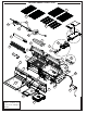
This outdoor built-in grill must be supported by the stainless-
steel hanger extending from the upper portion of the grill. The
hanger rests on the left, right, and back of the countertop and
on the two front structural supports with attached adjustable
screws located below the control panel on the gas grill side.
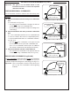
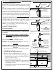
The control panel is designed to sit fl ush against the enclosure
front wall (see Fig. 20-2). If the non-combustible enclosure
countertop extends beyond the front wall, creating a countertop
overhang (see Fig. 20-1), it must be cut fl ush with the front
wall for the width of the control panel or a gap will be created
exposing the forward portions of the left and right side grill fi re
walls. Reference the MODEL SPECIFICATIONS section.
Note: It is not necessary to remove the control panel or
knobs to install this unit.
CONNECT THE GAS SUPPLY
For propane cylinders:
For connecting a propane unit to a portable propane tank,
read the safety warnings and follow the instructions in the
section SAFE USE AND MAINTENANCE OF PROPANE GAS
CYLINDERS.
Note: When a propane cylinder is installed inside of
the enclosure, the guidelines found in the GRILL
ENCLOSURE / VENTILATION REQUIREMENTS
section MUST be followed.
For household propane or natural gas units:
CAUTION: Use only C.S.A. listed stainless-steel flex
connectors within the enclosure.
WARNING
A rubber or plastic connector will rupture or leak, resulting
in an explosion or serious injury if used inside the appliance
enclosure.
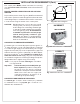
1. Run the attached fl ex connector routed under the middle
of the grill to the gas stub .
2. Turn OFF the gas supply at the source.
3. A shut-off valve is required within 6 feet of the unit.
If shut-off valve is connected to end of gas supply stub:
• Connect the fl ex connector to the shut-off valve (see
Fig. 20-3). Tighten securely.
If shut-off valve is installed in-line:
• Install the supplied fl are adapter to the gas supply using
a pipe joint compound resistant to all gasses (see Fig.
20-3). Tighten securely.
• Connect the fl ex connector to the fl are adapter (see Fig.
20-3). Tighten securely.
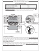
GAP CREATED
IDEAL
Flush-mounted
control panel
Proposed cut-
out in overhang
Countertop
Countertop
Overhang
Control panel
stops here
INSTALLATION
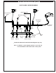
Fig. 20-3 Connecting to a gas line
Gas supply
Flare adaptor
(use on gas
supply stub only
if shut-off valve
installed in-line)
Flex connector
(coming from unit)
Shut-off valve
(required, not
included, must be
installed within 6
feet of the unit)
INCORRECT
Fig. 20-1 Countertop overhang - incorrect cutout
Fig. 20-2 Countertop overhang - correct cutout
CORRECT
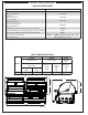
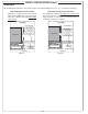
Fig. 20-4 Household propane & natural gas diagram
INSTALLATION
OFF
Shut-off valve (shown in-line)
must be within 6 feet of theunit
To gas
system
Cut-out
Countertop
Hanger
Flex
connector
Adapter
Gas inlet pipe