
Installation and Operating Instructions

3
NO. L-C2-27409
Rev 4 - 0901121556
INSTALLATION
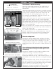
Built-in units
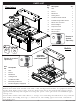
Prepare a cut-out in the countertop as specifi ed in
Table 1 and shown in Fig. 3-1. Note additional
clearance required to the rear for the blender cover
to open fully.
Install a listed, grounded 110-volt GFI receptacle
beneath the countertop within 5 feet of the blender
base so that the blender can be plugged into it.
Install the electrical junction box near the GFI
receptacle so that it can be plugged in the receptacle.
The wires from the box are already connected to the
beverage center.
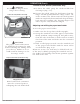
The transformer box must be put inside the enclosure
before the beverage center is installed.
After the enclosure cut-out and the electrical and
plumbing hookups are prepared, place the beverage
center into the cut-out. Keep all electrical wires from
being pinched between the beverage center and the
enclosure.
The beverage center will rest on the countertop by
its stainless-steel hanger and on the front support
shown in Fig. 3-1 underneath the face.
Silicon sealant may be applied around the top edge
of the countertop cut-out to create a barrier between
the housing and countertop capable of keeping out
fl uids. Do not use silicon between the blender base
and the stainless-steel housing, as the base must be
removable for cleaning and maintenance.
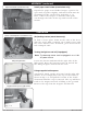
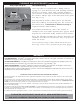
Stand-alone units
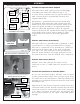
Locate the unit on a fl at, level surface near desired
electrical and water lines. To lock a caster press down
on the side of the lever with the word "OFF" stamped
on it until it stops and does not turn (see Fig. 3-2).
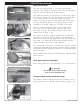
Repeat for all casters. For the stand-alone beverage
center, plug the end of an extension cord matching
the requirements on the cover into the left-most
electrical receptacle on the right side.
WARNING
This appliance must be
connected to a grounded
electrical source.
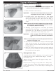
Fig. 3-1
4"
23-1/2"
12"
23 1/2"
Depth
Height
12"
Height
Depth
34"
Side view
Top view
Front view
36-1/2"
Width
Counter cut-out dimensions for built-in
(shown here with optional upper shelf)
Counter Cut-out Dimensions (Table 1)
Counter Opening Height*
12"
Counter Opening Width*
36-
3/4
"
Counter Opening Depth*
23-
1/2
"
Front
support
WARNING
Have all electrical work
performed by a licensed
professional electrician.
Caster in locked position (stand-alone only)
Fig. 3-2