
Installation Instructions and Owner's Manual

8
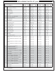
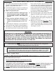
MODEL SPECIFICATIONS (cont.)
REV 2 - 1611101520
L-C2-435
Table 1 A430s A530s A540s A660s
Main burner quantity
N/P orifi ce drill size
2
#42 / #54
2
#40 / #53
3
#44 / #55
3
#42 / #54
Backburner *
N/P orifi ce drill size
#52 / #59 #52 / #59 #48 / #56 #48 / #56
Sideburner *
N/P orifi ce drill size
#50 / #58 #50 / #58 #50 / #58 #50 / #58
Infrared searing burner *
N/P orifi ce drill size
#49 / #56 #45 / #55 #49 / #56 #45 / #55
Wind defl ector model # (not included) 23728-18 23728-18 23732-18 23732-18
Burner maintenance kit model # (not included) MK-1
NAT to LP conversion kit (w/ tank tray) model # 24336-21
Input electrical requirements 120VAC / 15 AMP minimum / 60 Hz / GFCI outlet
Oven lights rating
12V / 10 watt halogen bulb
*
If equipped
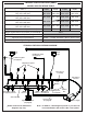
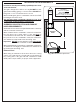
Note: In addition, a wire diagram specifi c to your unit can
be found affi xed to the inside of the control panel.
*
A660s model shown. Model wire
diagrams may vary.
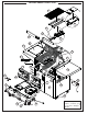
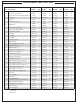
MODEL SPECIFICATIONS TABLE
Power supply
Wire harness
extension
Wire harness
assembly
Valve manifold
Ground
wire
Main burner igniters
STAND-ALONE GRILL WIRING DIAGRAM
Backburner igniter
(if equipped)
Oven
light
Oven
light
Light
switch
Meat probe
(if equipped)
Main
burner 1
Main
burner 2
Main
burner 3
Side burner
(if equipped)
Sideburner igniter
(if equipped)
*
Back burner
(if equipped)
Digital thermometer
(if equipped)
Thermocouple
(if equipped)