
Installation Instructions and Owner's Manual

32
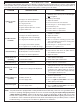
CONVERT GAS TYPE / CHECK BURNER ORIFICES (cont.)
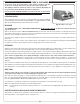
4. Remove the access plate by pulling the bottom
toward the front of the grill and rotating it upward
and outward until the two top tabs attached to back
wall of the oven can be removed from the slots in
the top of the plate.
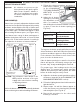
5. Remove the backburner
assembly retaining screw on
the lower left of the backburner
using a Phillips-head
screwdriver and set it aside.
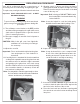
6. Pull out the wire from the
igniter electrode (Fig. 32-2),
then carefully remove the
backburner by slightly sliding it
to the left.
CAUTION: Be careful not
to damage the
wires connected
to the backburner
assembly.
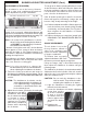
7. Use a
3
/
8
" hex nut driver
to remove the exposed
orifice. Check orifice. If
needed, replace it with the
correct orifi ce for the new
gas.
8. Replace the backburner assembly and reinsert the
retaining screw. Center the backburner assembly so
that the backburner plate will fi t over it. Tighten the
retaining screw using a Phillips-head screwdriver.
9. Replace the access plate by fi rst inserting the tabs
above into the slots in the top of the plate and then
rotating the bottom downward and inward.
10. Replace all the access plate screws using a Phillips-
head screwdriver.
Fig. 32-2
Backburner
orifi ce
Backburner
air shutter
Electrode
wire
Fig. 32-1
Retaining
screw
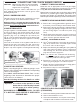
CONVERT/CHECK INFRARED BURNER
ORIFICE (IF EQUIPPED)
1. Remove the cooking grid from above the burner.
2. Unscrew both lighting tube hex head screws with a
3
/
8
" hex nut driver.
3. Remove the infrared burner by lifting the back of the
burner up so that both tabs are freed from their slots,
then lift the burner toward the back of the fi re box
and upward. Set the burner aside.
4. Use a
3
/
8
" hex nut driver to remove the exposed
orifi ce. Check orifi ce. If needed, replace it with the
correct orifi ce for the new gas.
5. Replace the infrared burner by fi rst sliding it over the
orifi ce, then lowering the two tabs under the back of
the burner into the slots in the back burner rest.
6. Reattach the lighting tube and replace the grid so
that the cut-out section is in front.
CONVERT/CHECK SIDE BURNER ORIFICE
1. Lift the side burner lid. Then remove the grill and
side burner cap and set them aside.
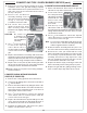
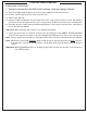
2. Locate and remove
the cotter pin from the
side burner assembly
underneath the side
burner shelf using
needle-nose pliers.
Set it aside.
3. From the top of the
side burner shelf, lift
the side burner upward while rotating the attached
tubing underneath away from the orifi ce near the
cart wall. Set it aside.
4. Use a
3
/
8
" hex nut driver to remove the exposed
orifi ce. Check orifi ce. If needed, replace it with the
correct orifi ce for the new gas.
Note: To protect the manifold threads when placing
the new orifi ce, start the threading manually,
and then tighten with the nut driver.
5. Rotate the burner assembly back into place over
the orifi ce and ensure it is fi rmly seated in the shelf.
6. Reinsert the cotter pin underneath the side
burner assembly using needle-nose pliers. It may
be necessary to push downward on the burner
assembly from above to fully expose the cotter
pin hole. Rotate the inserted cotter pin so that it
is fl ush with the underside of the shelf.
7. Replace the burner cap by centering it on the side
burner assembly and ensuring it drops in place.
8. Replace the grill with the grating running front to
back so that it drops fully down onto the shelf.
Fig. 32-3
Cotter
pin