
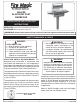
Installation and Operating Instructions

7
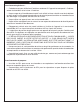
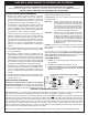
IN-GROUND PROCEDURE
The in-ground post is designed primarily for
installation with a permanent underground gas
supply. Read these instructions carefully and
completely before beginning the installation.
1. After running the underground gas supply line to
the planned barbecue
location, dig a hole for
the post and extension
approximately 18"
deep and 10-12" in
diameter.
Note: Run the gas supply
line up from the
bottom of the hole
(a little off center)
so that it reaches
to approximately 4
"
above ground level.
Note: The actual depth
of the hole should be such that the cooking
surface is 34-35
" above ground level.
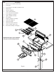
2. Unscrew the four (4)
screws and remove the
access plate in the back
of the barbecue post
using a No. 3 Phillips-
head screwdriver. Retain
the screws and access
plate for later.
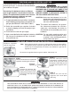
3. Verify that the gas supply line fi ts through the gas
line clearance hole in the bottom of the post (see Fig.
7-2). The clearance hole is the larger of the two
holes in the bottom of the post and is off center.
4. Verify that the fl exible
1
/
2
" gas connector coming
from the supply side of the safety timer valve will
connect properly with the gas supply line and
any necessary fl are or fi tting needed to make
the connection.
5. Attach the extension to the
bottom of the barbecue
post so that the open
portion is toward the back
of the barbecue and the
fi ve holes in the extension
line up with the fi ve (5)
weld-nuts in the post.
Ground level
Concrete level
Post
Gas supply
routes
Fig. 7-1
Fig. 7-2
Supply line
To safety-
timer valve
Tension bolt
Flex
connector
Fig. 7-3
Bolts
Weld-nut
To barbecue
6. From outside the joined post and extension, insert
one of the
1
/
4
X 20"-
5
/
8
bolts (supplied) into each
of the fi ve (5) bolt holes and tighten each using a
7
/
16
" socket driver or wrench (see Fig. 7-3).
Note: There is one hole on each side of the
post, except the back which has two holes
located on either side of the extension
opening.
Important: Verify that the gas supply line is running
up through the post hole, just off center.
It must extend high enough to reach
the barbecue gas connection and
remain safely above the level of the
concrete when poured.
Note: It may help to cover the end of the gas
supply line with a plastic bag and/or
masking tape to avoid getting concrete or
other debris in the supply line.
8. Pour the concrete into the hole 3-5" below
ground level taking care to protect the gas
supply line.
9. While the concrete is still wet, carefully lower the
barbecue post and attached extension into the
hole so that the gas supply line slides through
the clearance hole in the bottom of the post.
10. Orient the barbecue per plan, then level the
barbecue and support it so that it remains in
position while the concrete drys.
11. Connect the gas supply
line so that it runs
through the safety timer
valve located in the
middle of the post (and
regulator if equipped)
and test for leaks.
12. Re-attach the access plate to the back of the
barbecue post using the four original screws.
ABOVE GROUND GAS CONNECTIONS
To connect through the post, remove the knock-out disk
(see Fig. 7-4) at the bottom of the access plate with a
large standard screwdriver by inserting the screwdriver
into the notch provided in the center of the knock-out.
Remove the plastic grommet fastened to the inside of the
post (see photo on previous page) and insert it into the
newly created opening (Fig. 7-4) prior to passing the
gas connection through the opening.
When fi nished, replace the access plate and tighten
the four screws provided.
Access plate
Knock-out
Grommet (installed)
Fig. 7-4
POST ASSEMBLY AND INSTALLATION