
Installation and Operating Instructions

6
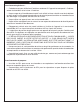
ENSURING PROPER COMBUSTION AIR AND
COOLING AIR FLOW
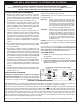
You must maintain proper air fl ow for the barbecue to
perform as it was designed (Fig. 6-1). If airfl ow is
blocked, overheating and poor combustion will result.
Do not block the 1" front air inlet along the bottom of
the face or more than 75% of the cooking grid surface
with objects such as pans or griddles.
Note: The 1" front air space beneath the face
allows access to the drip tray.
ELECTRICAL OUTLETS
All electrical outlets in the vicinity of the barbecue
must be properly grounded.
Note: Keep electrical supply cords away from all
heated surfaces.
PLANNING THE LOCATION OF THE POST BARBECUE
EXHAUST REMOVAL
If installed or used under
a patio roof, the cooking
grid area should be fully
covered by a chimney
and exhaust hood. An
exhaust fan with a rating
of 1,000 CFM (cubic
feet per minute) or more
may be necessary to effi ciently remove smoke and
other cooking by-products from the covered area.
This barbecue shall not be used under overhead
combustible construction. THIS UNIT SHOULD NOT
BE LOCATED IN A FULLY ENCLOSED AREA OF
ANY KIND.
This barbecue is designed FOR OUTDOOR USE ONLY.
DO NOT use this unit under unprotected fl ammable surfaces. DO NOT use this appliance
inside a building, garage, or any other enclosed area (see EXHAUST REMOVAL). This barbecue
must not be used in or on recreational vehicles or boats.
WARNING: This unit is NOT insulated and therefore during use it must be located with a minimum of 18" of
side and back clearance from unprotected combustible materials such as wood, plastic, or stucco
with wood framing.
GAS SUPPLY REQUIREMENTS
GAS SUPPLY PLUMBING REQUIREMENTS
For natural gas or a household propane system, rigid
1
/
2
", or
3
/
4
" black steel pipe, or local code approved
pipe is required to conduct the gas supply to the
unit. An outdoor approved fl exible connector can be
used to connect your household gas supply to the
barbecue. DO NOT use a rubber hose within the
enclosure for the barbecue unit. Apply only joint
compounds that are resistant to all gasses on all
male pipe fi ttings. Make sure to tighten every joint
securely.
Note: If
1
/
2
" pipe is used with natural gas, it
should be no longer than 20'.
Important: An external valve (with a removable
key) in the gas line is necessary for
safety when the barbecue is not in
use. It also provides for convenient
maintenance.
GAS SUPPLY AND MANIFOLD PRESSURES
For natural gas - normal 7" water column (w.c.),
minimum 5" w.c., maximum 10
1
/
2
" w.c.
For propane gas - normal 11" w.c., minimum 8" w.c.,
maximum 13" w.c.
Fig. 6-1
Ventilation diagram
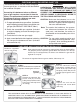
CONNECTING TO THE GAS SUPPLY
This post barbecue is
capable of connecting
to the gas supply in
a couple of different
ways. The connection
can be made inside the
post or out the back of
the post.
The gas must be
hooked up so that it
passes through the
timer (and regulator
if equipped) located
in the post. To access
the timer, unscrew and
remove the access plate in the back of the post using a
No. 3 Phillips-head screwdriver. Retain the screws.
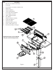
Post (access panel removed)
Back of timer valve
Flex connector
through hole in
base
Grommet
attached
with tie.
Location of
regulator if
equipped
(for natural
gas only)
Fig. 6-2
Adjustable
Nut
Tension
Bolt
Important: The tension bolt may have loosened
during shipping, use adjustable nut to
tighten, if necessary, before moving the
barbecue.