
User Manual


1. Overview Description
8
APS-6RF Instruction PN 50893:B 7/20/00
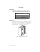
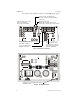
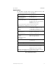
The figures below identify the features of the APS-6RF power supply:
Figure 2 APS-6RF Control Board
Figure 3 APS-6RF Main Board
J2
J9
J3
J1
TB2
JP3
JP2
Fuse F1 for AC protection
(4A, 3AG, slow blow)
Three 24 VDC output circuits
Two (2) power-limited
One (1) non power-limited
Trouble In (J4) - Trouble Out (J3)
“P” style connectors for internal cabinet
connections
LED Status Indicators:
Green LED – Indicates AC power on
Yellow LED – Indicates loss of AC or battery
Fuse F2 for battery protection
(10A, 3AG, slow blow)
Jumpers JP2 and JP3 for
selecting 8-hour or 16-hour
delay for AC loss reporting
(default is immediate)
APS-6Rsidebrd.cdr
JP1
Jumper JP1 for selecting AC input voltage
(120 VAC default)
APS-6Rboard.cdr