
User Manual

Appendix B: Sensiscan 2000 Connecting the APS-6RF to an MPS-24AF
20
APS-6RF Instruction PN 50893:B 7/20/00
Connecting the APS-6RF to an MPS-24AF
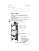
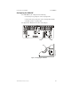
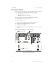
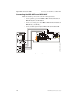
Make the following connections as shown in the figure below.
• Connect primary power from TB1 to MPS-24AF terminal block
TB1, Pin 5(
NEUT
) and Pin 7(
HOT
)
• Connect secondary power from TB3 to MPS-24AF terminal block
TB2, Pin 1(+) and Pin 2(–)
• Connect trouble input from J3 to MPS-24AF terminal block P5
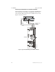
Figure 12 Wiring to MPS-24AF
P4
P3
JP5
TB1
TB2
F1CB1
P5
R27
P2
EA RTH G ND A C NE U TRA L A C HOT
+24 R CO M MON + 24 COMMO N
POWER LIM ITE D
BAT + BAT -
J2
J9
J3
J1
TB2
JP3JP2
APS-6R to MPS-24A.cdr