
User Manual

2. Installation Wiring the APS-6RF
14
APS-6RF Instruction PN 50893:B 7/20/00
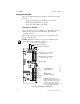
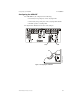
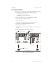
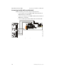
Connecting the APS-6RF to an IC-4F/ICE-4F Module
All four (4) NACs on the IC-4F are powered from the APS-6RF output
circuit 2 (J2) and the four (4) NACs on the ICE-4F are powered from
circuit 1 (J1). The NACs share the total 3A available from each circuit.
Typical connections for wiring:
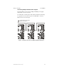
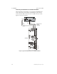
Figure 6 Typical APS-6RF Wiring to an IC-4F/ICE-4F Module
J65 J
J65 J
J2
J9
J3
J1
TB2
JP3
JP2
IC-4F
ICE-4F
Auxiliary Power
Harness
PN 71091
Black
Blue
Blue
Black
APS-6RF
APS-6Ricm.cdr