
User Manual
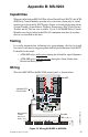
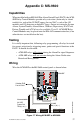
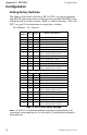
Table Of Contents
- 1. Introduction
- 2. Installation
- 3. Electrical Ratings
- Appendix A: MS-5210UD
- Appendix B: MS-9200
- Appendix C: MS-9600
ACM-8RF PN 50362:C 03/21/01
31
Appendix B: MS-9200
Capabilities
When installed with an MS-9200 Fire Alarm Control Panel (FACP), the ACM-
8RF Relay Control Modules provide relay activation (alarm only or alarm/
trouble) for each of the 56 FACP zones. Output activation for System Alarm,
System Trouble, Alarm Silence, Walktest, Supervisory, NAC Fault, Battery
Trouble and AC Fail are also available. Up to 32 ACM-8RF Relay Control
Modules may be placed onto the EIA-485 communication bus (if no other
devices are installed on the bus).
Testing
It is vitally important that, following relay programming, all relays be tested
for correct activation by triggering zones and/or special functions at the FACP.
It should also be noted:
• ACM-8RF relays will activate
during the Alarm Pre-signal Sequence.
• ACM-8RF relays will not activate
during the Alarm Verification
Retard and Reset periods.
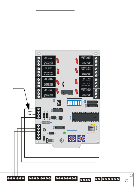
Wiring
Wire the AMC-8RF to the MS-9200 control panel as shown below.
Figure 16 Wiring ACM-8RF to MS-9200
24V UN REG 24 V NON RS 24V RS T
BE LL 2 PO WER
BE LL 1 PO WER
SUP V ALAR M TRO UBLE
PC/ PRINTE R
TERM COMM
+ - + - + -
B+ A + A- B- B+ A + A- B-
NO C NO NC C NO NC C
A B B+ A+ B- A-
1 CO MM 2
ACS
SHI ELD
SLC SL C
OUT+ IN+ OUT- IN-
T
B
4
T
B
2
T
B
1
T
B
3
T
B
7
T
B
5
T
B
6
12
OFF
1
2
3
45678
O
F
F
ACM-8RF
EIA-485
TB5 (+) & (–)
Nonresettable
24 VDC
Power Out
TB4(+) & (–)
MS-9200 Terminal Blocks
ACM8RF-ms9200.cdr
120 ohm ELR
Part #71244