
User Manual
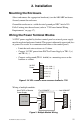
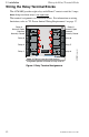
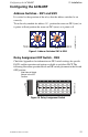
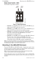
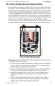
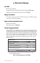
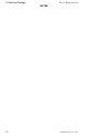
Table Of Contents
- 1. Introduction
- 2. Installation
- 3. Electrical Ratings
- Appendix A: MS-5210UD
- Appendix B: MS-9200
- Appendix C: MS-9600
ACM-8RF PN 50362:C 03/21/01
11
2. Installation
Mounting the Enclosure.
Select and remove the appropriate knockout(s) on the ABS-8RF enclosure.
Securely mount the enclosure.
Ground the enclosure to a solid electrical ground per NEC Article 250.
Pull all wiring into the enclosure (refer to "UL Power-limited Wiring
Requirements" on page 17).
Wiring the Power Terminal Blocks
24 VDC power supplied by the host control panel or external power supply
must be regulated and power-limited. This power is inherently supervised (loss
of power also results in a communication failure at the control panel).
• Limit the total wire resistance to 10 ohms.
• Connect 24 VDC power from FACP or Power Supply to TB1-3 (+)
and TB1-4 (–).
• Connect earth ground (TB1-1
EARTH
) to a mounting screw on the
backbox or cabinet.
Figure 2 24 VDC Power & Earth Ground Terminals - TB1
Wiring of multiple modules.
Figure 3 Multiple Module Wiring
2
24 V (+)
1
EARTH
5
SYS COM (–)
TB1
4
SYS COM (–)
3
24 V (+)
ACM8RF-TB1.cdr
24 VDC
Power
2
1
5
TB1
4
3
2
1
5
TB1
4
3
– 24 VDC
+ 24 VDC
First ACM-8RF -- -- -- -- -- -- Last ACM-8RF
Host FACP or Remote
Power Supply
ACM8RF-power.cdr