
Manual

24 411UDAC Manual — P/N 51073:E 9/20/2013
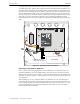
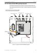
Installation Input Channels
CAUTION!
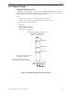
HIGH VOLTAGE
COMM. FAIL
BATT FAULT
SYSTEM
TROUBLE
SUPV.
AC PWR
ACTIVE
GND FAULT
B+ A+ B- A- A B
Slc Slc Slc Slc Shield
NO NC C NO NC C NC NO C
411UDAC
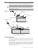
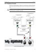
Note: The addressable monitor module input, which is
being used to monitor the 411UDAC Relay Output
programmed for DACT Trouble must be programmed as
'DACT Trouble' at the FACP. The 411UDAC must be
programmed as a Slave Communicator (programming
address 64 set to ‘2’)
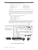
Addressable FACP (must be UL-listed for Central Station Service and Remote Signaling Service)
411UDAC Relay 2 Output (DACT Trouble)
Channel 2/Zone 2
Channel 1/Zone 1
Channel 3/Zone 3
2.2K ELR Channel 4
2.2K
ELR
Monitor Circuit Input
SLC Loop
Trouble Relay
Alarm Relay
Supervisory Relay
UL listed
2.2K ELRs
P/N 27070
Program the 411UDAC as follows:
Channel 1 - Normally Open Contact Device (alarm)
Channel 2 - Host Panel Trouble
Channel 3 - Supervisory
9200udlsc411a.wmf
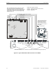
Monitor
Module*
ELR
supplied
with
Monitor
Module
*If the SLC device does not
match the one in this figure,
refer to the SLC manual
wiring conversion charts for
legacy and newer versions of
the modules.
Figure 2.6 Typical Addressable FACP Connection to 411UDAC