
Manual

411UDAC Manual — P/N 51073:E 9/20/2013 13
Circuits Product Description
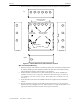
1.3 Circuits
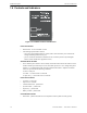
The 411UDAC circuit board contains a MicroController Unit (MCU), dual modular phone line
jacks, piezo sounder, and connectors for input, output and power wiring. A piezo silence switch
and reset switch are provided on the membrane panel which plugs into connector J7 on the main
circuit board.
1.3.1 Channels/Inputs
Four input channels are provided on the 411UDAC. The 411UDAC can be used to monitor a host
FACP (Fire Alarm Control Panel) in Slave Mode or as a stand-alone FAC (Fire Alarm Communica-
tor). Each input can be programmed to monitor the following conditions:
• fire alarm activation
• 4-wire smoke (channels 1 & 3 only)
• pull station
• normally open contact device
• waterflow
• trouble activation
• fire supervisory activation
1.3.2 Notification Appliance Circuit
One Style B NAC (Notification Appliance Circuit) requiring a 2.2K ohm End-of-Line resistor.
This NAC can only be used to supplement host panel NACs.
1.3.3 Output Circuits
• Modular jacks are used to interface the primary and secondary phone lines to the public
telephone network. Phone lines are fully supervised at all times (if communication is enabled).
• 12 volt resettable special application power output (200 mA)
• 12 volt battery charger will charge up to 14 AH batteries
1.3.4 Auxiliary Relays
Two dry Form-C relays (P/N: 411RK), with contacts rated for 2.0 amps @ 30 VDC (resistive) or
0.5 amps @ 30 VAC (resistive), are installed on the main circuit board. Each relay is programma-
ble for:
Alarm
Fire supervisory - latching
Fire supervisory - autoresettable
Host panel trouble
DACT trouble
Total communications failure
1.3.5 Earth Ground
Connect a separate earth ground wire to ground stud in backbox for transient protection (refer to
Figure 2.3 on page 21 for location of stud).