Fire Alarm Communicator 411UDAC Manual Document 51073 9/20/2013 P/N 51073:E Rev: E ECN 13-786
Fire Alarm & Emergency Communication System Limitations While a life safety system may lower insurance rates, it is not a substitute for life and property insurance! An automatic fire alarm system—typically made up of smoke detectors, heat detectors, manual pull stations, audible warning devices, and a fire alarm control panel (FACP) with remote notification capability—can provide early warning of a developing fire.
Installation Precautions Adherence to the following will aid in problem-free installation with long-term reliability: WARNING - Several different sources of power can be connected to the fire alarm control panel. Disconnect all sources of power before servicing. Control unit and associated equipment may be damaged by removing and/or inserting cards, modules, or interconnecting cables while the unit is energized. Do not attempt to install, service, or operate this unit until manuals are read and understood.
Software Downloads In order to supply the latest features and functionality in fire alarm and life safety technology to our customers, we make frequent upgrades to the embedded software in our products. To ensure that you are installing and programming the latest features, we strongly recommend that you download the most current version of software for each product prior to commissioning any system.
Table of Contents Section 1: Product Description ............................................................................................. 10 1.1: Product Features ..........................................................................................................................................10 1.2: Specifications...............................................................................................................................................12 1.3: Circuits.........................
Table of Contents Ademco Contact ID Format Primary Central Station Event Codes .....................................................37 4+2 Standard and 4+2 Express Formats Primary Central Station Event Codes...................................38 All 3+1, 4+1 and 4+2 Expanded Formats Primary Central Station Event Codes ................................39 Primary Central Station Number Account Code (21 - 24) ...................................................................
Table of Contents Section 4: Central Station Communications ........................................................................ 54 4.1: Transmittal Priorities ...................................................................................................................................57 4.2: Ademco Contact ID Format Event Code Description .................................................................................57 Section 5: Remote Site Upload/Download.....................................
This digital communicator/transmitter has been designed to comply with standards set forth by the following regulatory agencies: • Underwriters Laboratories • NFPA National Fire Protection Association Before proceeding, the installer should be familiar with the following documents.
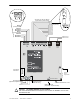
Relay 2 (nonsupervised) Common NC Contact NO Contact Relay 1 (nonsupervised) Common NC Contact NO Contact CAUTION! CAUTION! GND FAULT 411udab2.wmf Phone Line 1 Phone Line 2 HIGH VOLTAGE Transformer Connection 411anac.wmf 411arel.
Section 1: Product Description The 411UDAC is a fire alarm communicator with four input/channels and dual telephone lines. The four inputs use conventional input devices. The 411UDAC accepts waterflow devices, fourwire smoke detectors, pull stations and other normally-open contact devices. The unit also supervises AC voltage, telephone line input voltage/current, battery level and battery charger operation.
Product Features Product Description • Separate external keypad and display provides means of programming 411UDAC in program mode provides means of testing input/output circuits (including telephone connections) in Troubleshoot Mode • Compact in size 14.5" (36.83 cm) high X 12.875" (32.7 cm) wide X 4.5" (11.
Product Description Specifications 1.2 Specifications AC Power - TB3 120 VAC, 60 Hz, 0.7 amps Wire size: minimum 14 AWG (2.00 mm2) with 600V insulation Supervised, nonpower-limited Battery (lead acid only) - J3 Maximum Charging Circuit: Float charge - 13.6V @ 3.
Circuits Product Description 1.3 Circuits The 411UDAC circuit board contains a MicroController Unit (MCU), dual modular phone line jacks, piezo sounder, and connectors for input, output and power wiring. A piezo silence switch and reset switch are provided on the membrane panel which plugs into connector J7 on the main circuit board. 1.3.1 Channels/Inputs Four input channels are provided on the 411UDAC.
Product Description Controls and Indicators 411udacdsp.wmf 1.4 Controls and Indicators Figure 1.
Components and Accessories Product Description 1.5 Components and Accessories Main Circuit Board The main circuit board contains the system’s MCU (microcontroller unit), power supply, other primary components and wiring interface connectors. The main circuit board is shipped in the same carton as the cabinet but is not mounted in the cabinet. The circuit board should be installed only after the cabinet is mounted to the wall and the area is clean and free of potential contaminants.
Product Description Panel Configuration 1.7 Panel Configuration The 411UDAC can be configured, through programming, for the following modes of operation: • Stand-alone Mode With Communicator Enabled - the 411UDAC functions as a latching digital alarm communicator in which all input circuit activations latch (except those programmed as autoresettable) and are restored only by pressing the local reset switch.
Telephone Requirements and Warnings Product Description 1.9 Telephone Requirements and Warnings 1.9.1 Telephone Circuitry - PH1 & PH2 AC Ringer Equivalence Number (REN) = 0.4B Mates with RJ31X Male Connector Supervision Threshold: less than 5.0 volts for 2 minutes The REN is used to determine the quantity of devices which may be connected to the telephone line. Excessive RENs on the telephone line may result in the devices not ringing in response to an incoming call.
Section 2: Installation 2.1 Mounting Options The cabinet may be either semi-flush or surface mounted. The door is removable during the installation period by opening and lifting it off the hinges. The cabinet mounts using two key slots and two additional 0.25" diameter holes located in the backbox. The keyslots are located at the top of the backbox and the two securing holes at the bottom. Carefully unpack the system and check for shipping damage.
Mounting Installation 7. Mount the backbox to the keyhole mounting bolts, install and tighten the remaining fastener. Top Mounting Keyholes 10.0” (25.4cm) Main Circuit Board Mounting Studs Ground Stud Mounting Holes 411udaccab.wmf Transformer Mounting Studs Left side Right side Bottom Figure 2.1 Cabinet Dimensions and Knockout Locations Main Circuit Board Mounting 1.
Installation Operating Power 5. When wiring is completed, re-install the door. Top Depth=4.533” (11.51cm) Door = 13.047” (33.14cm) Backbox = 12.875” (32.7cm) 411accab2.wmf Door = 14.760” (37.49cm) Backbox = 14.5” (36.83cm) Right Side Left Side Bottom Figure 2.2 411UDAC Backbox 2.3 Operating Power ! CAUTION: DISCONNECT POWER BEFORE SERVICING SEVERAL DIFFERENT SOURCES OF POWER CAN BE CONNECTED TO THE 411UDAC. DISCONNECT ALL SOURCES OF POWER BEFORE SERVICING THIS UNIT.
Operating Power Installation CAUTION! A separate earth ground connection must be made to ensure proper panel operation and lightning and transient protection. Remove the two keps nuts from the grounding stud in the backbox. Connect the incoming earth ground wire to supplied cable #71073 with a wire nut. Position the ring terminal end over the grounding stud. Secure with one of the keps nuts.
Installation Input Channels When the panel is ready to have power applied, connect the battery cable plug to connector J3 on the 411UDAC main circuit board. The battery charger is capable of recharging sealed lead acid type batteries. Refer to the battery calculations table to determine the correct battery rating. ! CAUTION: BATTERY CONTAINS SULFURIC ACID THE BATTERY CONTAINS SULFURIC ACID WHICH CAN CAUSE SEVERE BURNS TO THE SKIN AND EYES, AND CAN DESTROY FABRICS.
Input Channels Installation The channel/inputs may be programmed as shown below: • 4-wire smoke detector (inputs 1 & 3 only) • Supervisory • Pull station • Supervisory autoresettable • Normally-open contact device • Waterflow silenceable • Host panel trouble • Waterflow nonsilenceable A maximum of five waterflow devices may be used on any circuit programmed as a waterflow zone per NFPA 72. It is allowable to mix an assortment of device types (i.e.
Installation Input Channels Program the 411UDAC as follows: Channel 1 - Normally Open Contact Device (alarm) Channel 2 - Host Panel Trouble Channel 3 - Supervisory Note: The addressable monitor module input, which is being used to monitor the 411UDAC Relay Output programmed for DACT Trouble must be programmed as 'DACT Trouble' at the FACP.
Output Circuits Installation 2.5 Output Circuits Notification Appliance Circuit The 411UDAC provides one Style Y (Class B) NAC (Notification Appliance Circuit). The NAC is supervised and power-limited and is capable of 1.0 amp of current. Refer to the Device Compatibility Document for a listing of compatible notification appliances. Notes: 1. The 411UDAC can only be used to supplement host panel NACs. 2. Do not connect strobes to the 411UDAC Notification Appliance Circuit.
Installation Output Circuits Relay Programming The relays are programmable for activation on fire alarm, host panel trouble, fire supervisory, total communication failure and DACT. Refer to “DACT Programming” on page 36. Addresses ‘85 88’ are used for programming relay functions and enable. Note: Relay connections may be power-limited or nonpower-limited. However, connecting one type next to the other type is not allowed. Both circuits must be either power-limited or nonpower-limited.
Telephone Circuits Installation 2.6 Telephone Circuits Provision to connect two independent telephone lines is available via two telephone jacks labeled PH1 (Primary) and PH2 (Secondary). Telephone line control/command is possible via double line seizure as well as usage of an RJ31X style interconnection. (RJ31X jacks must be ordered separately). ! CAUTION: PROPER FUNCTIONALITY IT IS CRITICAL THAT THE 411UDAC BE LOCATED AS THE FIRST DEVICE ON THE INCOMING TELEPHONE CIRCUIT TO PROPERLY FUNCTION.
Installation Optional Programmer 2.
UL Power-limited Wiring Requirements Installation 2.8 UL Power-limited Wiring Requirements Power-limited and nonpower-limited circuit wiring must remain separated in the cabinet. All power-limited circuit wiring must remain at least 0.25” away from any nonpower-limited circuit wiring. Furthermore, all power-limited and nonpower-limited circuit wiring must enter and exit the cabinet through different knockouts and/or conduits. A typical wiring diagram for the 411UDAC is shown below.
Section 3: Modes of Operation The 411UDAC has five operational modes: • Normal Mode • Real Time Clock Mode • Program Mode (requires password) • Troubleshoot Mode • Default Mode (requires password) The operational mode for the 411UDAC is Normal Mode. The operator is able to switch between any modes of operation provided no alarm events are active in the system. It should be noted that the unit will not respond to input activations while in any mode except Normal Mode. Some modes require a password.
Normal Mode Modes of Operation The 411UDAC meets NFPA 72 requirements for Remote Station Protective Signaling Service and Central Station Signaling Service reporting requirements for: (a) the type of signal, (b) condition and (c) location of the reporting premises. See “Central Station Communications” on page 54, for additional information.
Modes of Operation Password Creation and Entry 1st EVENT KEY This key, along with the UP and DOWN arrow keys, are used only in Program Mode. Press the 1st EVENT key at any time to display the first program memory address and its content. The following may be displayed on the Programmer: 00_F (address) (data) If the 1st EVENT key is pressed a second time, the following will be displayed on the Programmer display: 0.
Real Time Clock Mode Modes of Operation 3. For the initial power-up of the 411UDAC or for the first power-up after a manually defaulted password, key in the default password 0000 and press [ENTER/STORE]. The display will then read dC_P. 4. Press d to continue with the default password or press C to change to a new password. 5. If d is entered in step 4, the display goes directly to the programming/default modes. 6. If C is entered in step 4, the display will read En_P prompting for a new password.
Modes of Operation Program Mode Enter the second hour digit (4 in this example) and press the [ENTER/STORE] key. The number '4' will appear as the digit second from the left and the decimal point will move one position to the right indicating that the third digit from the left is now ready for programming. 140.1 Digit to be programmed Enter the first minute digit (0 in this example) and press the [ENTER/STORE] key.
Program Mode Modes of Operation The user must program the primary and secondary phone numbers, account numbers, 24-hour test report times and verify event codes for each Central Station account. The 411UDAC is shipped with the program options/features already factory programmed. Alternative options/features may be programmed if desired. If all factory default settings are acceptable, programming is complete.
Modes of Operation Program Mode The Programmer cable should not be removed from the 411UDAC unless the unit is in Normal Mode. If the Programmer cable is removed while the 411UDAC is in a Mode other than Normal Mode, the communicator will automatically revert to Normal Mode following a 10 minute time-out period. Note that if the Programmer is in Troubleshoot Mode when the cable is removed, the 411UDAC will revert to Normal Mode following a 20 minute time-out period. 3.4.
Program Mode Modes of Operation 9: 4+1 Expanded 1900 Hz Carrier, 1400 Hz ACK A: 4+2 Standard 1800 Hz Carrier, 2300 Hz ACK B: 4+2 Expanded 1800 Hz Carrier, 2300 Hz ACK C: 4+2 Standard 1900 Hz Carrier, 1400 Hz ACK D: 4+2 Expanded 1900 Hz Carrier, 1400 Hz ACK E: Contact ID, DTMF, 1400/2300 ACK F: Future use Consult the Central Station for proper Format selection. For any Format chosen, all event codes are automatically programmed by the 411UDAC. Refer to Table 3.
Modes of Operation Program Mode Address Description 175 -177 Primary # Low Battery Fault Event Code Setting Channel/Input # 302 000 178 - 180 181 - 183 Primary # No Battery Fault Event Code 311 000 Primary # Phone Line 1 Voltage Fault Event Code 351 000 184 - 186 Primary # Phone Line 2 Voltage Fault Event Code 352 000 187 - 189 Primary # NAC Fault Event Code 321 000 190 - 192 Primary # Charger Fault Event Code 300 000 193 - 195 Primary # Phone Number 1 Communication Fault Event
Program Mode Modes of Operation Address Description 197 - 198 Primary # Input Channel 4 Fault Restore Code Setting 199 - 200 Primary # AC Voltage Fault Restore Code 93 201 - 202 Primary # Earth Fault Restore Code A1 203 - 204 Primary # Low Battery Fault Restore Code A2 205 - 206 Primary # No Battery Fault Restore Code A3 207 - 208 Primary # Phone Line 1 Voltage Fault Restore Code A4 209 - 210 Primary # Phone Line 2 Voltage Fault Restore Code A5 A6 D4 211 - 212 Primary # NAC Fault R
Modes of Operation Address Program Mode Description Setting 171 Primary # Input Channel 4 Fault Restore Code 172 Primary # AC Voltage Fault Restore Code D 9 173 Primary # Earth Fault Restore Code A 174 Primary # Low Battery Fault Restore Code A 175 Primary # No Battery Fault Restore Code A 176 Primary # Phone Line 1 Voltage Fault Restore Code A 177 Primary # Phone Line 2 Voltage Fault Restore Code A 178 Primary # NAC Fault Restore Code A 179 Primary # Charger Fault Restore Code 1
Program Mode Modes of Operation Enter the remaining numbers in their respective addresses as shown below: Entry 4 8 4 7 1 6 1 F F F F F Address 30 31 32 33 34 35 36 37 38 39 40 41 F F F F F F 42 43 44 45 46 47 F F 48 49 Valid entries for both the primary and secondary phone numbers are 0 to 9 and A to F with the numeric digits as dialed numbers and the hexadecimal digits representing the following functions: • A = * on a Touch-Tone phone keypad • B = # on a Touch-Tone phone
Modes of Operation Program Mode Upon accessing the first event code address which is 229 (Table 3.5, “4+2 Standard and 4+2 Express Formats - Secondary,” on page 43), the following may be displayed on the Programmer’s 7-Segment Display, if the corresponding Format was selected in address 50. 2291 (address) (data) The first three locations on the left of the Programmer’s display represent the memory address 229.
Program Mode Modes of Operation 4+2 Standard and 4+2 Express Formats Secondary Central Station Event Codes If 1, A or C is entered for address 50, the following data is automatically programmed for the Secondary Central Station phone number event codes. Enter '00' for the Setting to disable the report to the Central Station.
Modes of Operation Program Mode All 3+1, 4+1 and 4+2 Expanded Formats Secondary Central Station Event Codes If 0, 2, 3, 4, 5, 6, 7, 8, 9, B or D is entered for address 50, the following data is automatically programmed for the Secondary Central Station phone number event codes. Enter '0' for the Setting to disable the report to the Central Station.
Program Mode Modes of Operation Secondary Central Station Number Account Code (51 - 54) The four locations at addresses 51 - 54 default to all '0's. Valid entries are 0 - 9 and A - F. The number of digits entered must match the format selection. If programming '2, 3, 4 or 5' into address 50, enter three digits (one digit each in locations 51, 52 and 53 - location 54 is ignored). If programming '0, 1, 6, 7, 8, 9, A, B, C, D or E' into address 50, enter four digits (one each in locations 51, 52, 53 and 54).
Modes of Operation Program Mode Address 64 Setting 411UDAC Operational Mode 411UDAC Function 0 Stand-alone/Communicator Disabled latching inputs/onboard communicator disabled 1 Stand-alone/Communicator Enabled latching inputs/onboard communicator enabled 2 Slave/Communicator Enabled non-latching inputs/onboard communicator enabled 3 Slave/Communicator Disabled non-latching inputs/onboard communicator disabled Table 3.
Program Mode Modes of Operation Input Channel 3 Delay Timer (75 - 77)1 The Delay Timer is used to delay digital communicator transmission to a Central Station when the Input Channel is activated. Input Channel 3 Delay Timer is factory set to '000' seconds for no delay. The timer may be programmed for a delay of from 0 to 179 seconds. Inputs programmed for fire alarm, pull station, host control panel trouble and fire supervisory, must not be delayed.
Modes of Operation Program Mode Reserved for Future Use (89) Leave default setting of '0' Panel Unlock (90) The communicator must be unlocked to accept a remote upload/download. Leaving the default setting of '0' will require the unlock code 8655 be entered for each data transfer session (30 minute timeout). Enter ‘1’ to keep the communicator in a permanent unlocked state. Alarm Verification Enable (91) Alarm verification works only on zones programmed as 4-wire smoke detector zones (i.e.
Program Mode Modes of Operation Restoral Method (94) Restoral Method refers to the communication of Restoral Events to a Central Station. It has no effect on the actual input circuit restoral itself. • Typical Restoral Method - ‘0’ entry programs the panel to transmit each input circuit restoral, as it occurs, to the Central Station. In Slave Mode, this means that as soon as an input restores, the communicator will immediately transmit the Restoral Event to the Central Station.
Modes of Operation Program Mode Table 3.8 describes the events that would take place after the reset period, according to each unique Communicator Restoral Method. It is assumed that an input circuit is active before reset. Input Circuit After Reset SHORTED NOT SHORTED Typical Restoral Method Conditional Restoral Method #1 Conditional Restoral Method #2 All local annunciation of the active event stops. The short is rediscovered after reset period and local annunciation begins again.
Default Mode Modes of Operation Service Terminal 1 Phone Number (101 - 120) Addresses 100 - 119 are reserved for the Service Terminal Number 1 phone number. Factory default is all 'F's. Valid entries are 0 - 9 plus A, B, C, D and E. Use 'F' to designate the end of the phone number. See “Remote Site Upload/Download” on page 60 for additional information.
Modes of Operation Troubleshoot Mode If an incorrect key is entered, reenter the proper 4-digit code before pressing the [ENTER/STORE] key. Within five seconds, repeat this entry by again pressing the MODE key followed by the 4-digit code 3337 and pressing the [ENTER/STORE] key. The display will read LinP. Enter your 4-digit password. When reprogramming is complete, the real time clock will display. 3.
Troubleshoot Mode Modes of Operation Telephone Line Testing Press C for touchtone dialing or D for rotary dialing, followed by [ENTER/STORE]. The Programmer keypad may be used as a telephone touchpad for number dialing. Once the first digit is pressed, the display will move the C or D character one position to the left, while placing the next digit to be dialed on the farthest right display position. Continue to press the phone numbers to be dialed. The dialer stores the digits as they are pressed.
Section 4: Central Station Communications The 411UDAC transmits system status reports to Central Stations via the public switched telephone network. Two supervised telephone line connections are made to interface the communicator to the telephone lines. Two 7-foot telephone cords P/N MCBL-7 may be used for this purpose (not supplied - order separately). The digital communicator supervises both telephone lines for proper voltage.
Central Station Communications The digital communicator is capable of reporting detailed messages depending upon the Format in use. Table 4.1 shows the data reporting structure for each of the pulsed formats as well as the Ademco Express Formats. Ademco Express Formats allow a typical data message to be transmitted to the Central Station in under 5 seconds. Pulsed formats typically require 15 to 20 seconds in comparison. Table 4.2 defines each letter code used in Table 4.1 .
Central Station Communications Where: SSS or SSSS = Subscriber ID FA = Fire Alarm (1st digit) FA2 = Fire Alarm (2nd digit) Z = Channel/Input Number RFA = Fire Alarm Restore (1st digit) RFA2 = Fire Alarm Restore (2nd digit) TZ = Zone Trouble (1st digit) TZ2 = Zone Trouble (2nd digit) RTZ = Zone Trouble Restore (1st digit) RTZ2 = Zone Trouble Restore (2nd digit) TS = System Trouble (1st digit) TS2 = System Trouble (2nd digit) RTS = System Trouble Restore (1st digit) RTS2 = System T
Transmittal Priorities Central Station Communications 4.1 Transmittal Priorities The digital communicator transmits highest priority events first. Events in terms of priority are listed below in descending order: 1. Fire Alarm (highest priority level) 2. Fire Supervisory 3. System Troubles – Host Panel Trouble (active input programmed for trouble) – AC Fail (after delay) – Channel/Input faults – Telephone line fault – Communication trouble – System Off Normal 4.
Central Station Communications Ademco Contact ID Format Event Code Description Ademco Contact ID Reporting Structure A typical printout from a Central Station receiver (such as the Ademco 685) of alarm and trouble reports in the Ademco Contact ID Reporting Structure follows: 58 Time Date Rcvr/Line ID SSSS QXYZ GG CCCC 11:28 03/25 11 7777 E110 00 C001 - general fire alarm on Channel/Input 1 11:28 03/25 11 7777 E111 00 C002 - smoke detector alarm on Channel/Input 2 11:28 03/25 11 77
Ademco Contact ID Format Event Code Description Central Station Communications Ademco 685 (2) Silent Knight 9800 (4) Osborne Hoffman 2000E (5) Radionics 6600 (6) Surgard System III (7) Surguard MLR-2 (8) Surguard MR-2000 (9) Ademco MX8000 (10) 0 4+1 Ademco Express 1 4+2 Ademco Express 2 3+1/Standard/1800/2300 3 3+1/Expanded/1800/2300 4 3+1/Standard/1900/1400 5 3+1/Expande
Section 5: Remote Site Upload/Download The 411UDAC may be programmed off site via the public switched telephone network. Any personal computer with Windows® XP or greater Upload/Download software P/N PK-411UD (available on PK-CD or online), may serve as a Service Terminal. For details on the remote site upload/download software package, refer to the PK-411UD Manual.
General Remote Site Upload/Download • Contact with callback disabled - The Service Terminal calls the communicator. No hang-up sequence occurs. Data transfers proceed. Note that Callback enable/disable is controlled by the master user at the Service Terminal on a per call basis.
Remote Site Upload/Download Downloading to the Communicator Callback to Service Terminal Any time that the communicator is remotely requested to allow an upload or download with callback, it will confirm the source of the incoming call, hang-up and call the calling party (Service Terminal phone number) back. Error Checking As each block of data is received by the communicator, it is checked for accuracy. If an error is detected, the block is retransmitted until correct, up to a maximum of four times.
Simultaneous Data Transfers • Troubleshoot system voltages in real-time or as a 'snapshot' • Current system status in real-time continuous or as a 'snapshot' Remote Site Upload/Download Uploading is possible at any time provided the following conditions are true: The communicator may be in any mode of operation. Uploading is not possible if the communicator is active or while testing the phone lines while in Troubleshoot Mode.
Section 6: Battery Calculations Use the Total Standby and Alarm Load Currents calculated in Tables 6.2, and 6.3, for the following battery calculations. Standby Load Current in amps (from Table 6.2 ) [ ] Alarm Load Current in amps (from Table 6.3 ) [ ] Required Standby Time in Hours (24 or 60 Hours) X [ ] = __________ = __________ Required Alarm Time in Hours (i.e. 5 min. = 0.
411UDAC Power Supply Battery Calculations 6.1 411UDAC Power Supply The 411UDAC provides filtered power for operating the digital communicator, external devices and the battery charger. The power for operating external devices is limited. Use Table 6.2 (standby or nonalarm) and Table 6.3 (alarm) to determine if external loading is within the capabilities of the power supply.
Appendix A: Programming Sheets A.1 Digital Communicator Options Program Sheets To enter Programming Mode, press the MODE key, 7764, and then the [ENTER/STORE] key. 00 01 02 03 04 05 06 07 08 09 10 11 12 13 14 15 16 17 18 19 Addresses 00 to 19 store the Primary Central Station phone number. Enter 'F' to represent the end of number. Primary Central Station Communication Format: Valid entries are 0 to 9 and A to F.
Digital Communicator Options Program Sheets Programming Sheets 78 79 80 Input Channel 4 Delay Timer. Enter 0 - 179 seconds delay. Factory default is '000' for no delay. Does not delay Input Channels programmed for fire functions. 81 Touchtone/Rotary Select for Primary Phone. Enter '0' for touchtone dialing; '1' for rotary dialing. 82 Make/Break Ratio for Primary Phone. Enter '0' for 67/33 ratio; '1' for 62/38 ratio. 83 Touchtone/Rotary Select for Secondary Phone.
Programming Sheets Digital Communicator Options Program Sheet (Factory Defaults) A.2 Digital Communicator Options Program Sheet (Factory Defaults) To enter Programming Mode, press the MODE key, 7764, and then the [ENTER/STORE] key. F F F F F F F F F F F F F F F F F F F F 00 01 02 03 04 05 06 07 08 09 10 11 12 13 14 15 16 17 18 19 Addresses 00 to 19 store the Primary Central Station phone number. Enter 'F' to represent the end of number.
Digital Communicator Options Program Sheet (Factory Defaults) Programming Sheets 0 Reserved for future use. Leave default setting of ‘0.’ 0 Panel unlock. ‘0’ for password unlock. 0 Alarm verification. '0' to disable. 0 Silence inhibit. '0' to disable. 0 Autosilence. '0' to disable. 0 Restoral method. '0' for Typical restoral method. 0 Coding, Notification Appliance Circuit. ‘0’ for no coding (steady). 0 Trouble Call Limit - Dialer Runaway Prevention Feature. '0' for disabled feature.
Appendix B: Event Codes/Transmission Format Programming Sheets To enter Programming Mode, press the MODE key, 7764 and then the [ENTER/STORE] key. B.
4+2 Standard & 4+2 Express Formats Primary Central Station Event Codes/Transmission Format Programming Sheets --To enter Programming Mode, press the MODE key, 7764 and then the [ENTER/STORE] key. B.
Event Codes/Transmission Format Programming SheetsAll 3+1, All 4+1 and 4+2 Expanded Formats for Primary Central Station To enter Programming Mode, press the MODE key, 7764 and then the [ENTER/STORE] key. B.
Ademco Contact ID Format Primary Central Station Event Codes/Transmission Format Programming Sheets --To enter Programming Mode, press the MODE key, 7764 and then the [ENTER/STORE] key. B.
Event Codes/Transmission Format Programming Sheets Ademco Contact ID Format Primary Central Station (Factory Defaults) B.
Appendix C: Ademco Contact ID Format Event Code Description EVENT CODE CLASSIFICATIONS 100 ALARMS Medical Fire Panic Burglary General 24 Hour 200 SUPERVISORY Fire 300 TROUBLES 400 OPEN/CLOSE REMOTE ACCESS System Sounder/Relay System Peripheral Communication Protective Loop Sensor EVENT Open/Close Remote Access Access Control 500 DISABLES/ BYPASSES System Sounder/Relay System Peripheral Communication 600 TEST/MISC.
Ademco Contact ID Format Event Code Description EVENT MESSAGE 137 Tamper BURG - Tamper - # 138 Near Alarm BURG - Near Alarm - # General Alarms - 140 140 General Alarm ALARM - General Alarm - # 141 Polling loop open ALARM - Polling Loop Open - # 142 Polling loop short ALARM - Polling Loop Short - # 143 Expansion module failure ALARM - Exp. Module Fail - # 144 Sensor tamper ALARM - Sensor Tamper - # 145 Expansion module tamper ALARM - Exp.
Ademco Contact ID Format Event Code Description EVENT MESSAGE 323 Alarm relay TROUBLE - Alarm Relay 324 Trouble relay TROUBLE - Trouble Relay 325 Reversing TROUBLE - Reversing Relay 326 Bell 3 TROUBLE - Bell/Siren #3 327 Bell 4 TROUBLE - Bell/Siren #4 System Peripheral Troubles - 330 and 340 330 System Peripheral TROUBLE - Sys. Peripheral - # 331 Polling loop open TROUBLE - Polling Loop Open 332 Polling loop short TROUBLE- Polling Loop Short 333 Expansion module failure TROUBLE - Exp.
Ademco Contact ID Format Event Code Description EVENT MESSAGE 412 Success - download/access REMOTE - Successful Access Restore not applicable 413 Unsuccessful access REMOTE - Unsuccessful Access Restore not applicable 414 System shutdown REMOTE - System Shutdown 415 Dialer shutdown REMOTE - Dialer Shutdown 416 Success - upload/access REMOTE - Successful Access Restore not applicable 421 Access denied ACCESS - Access Denied - User # Restore not used 422 Access report by user ACCESS - Acces
Appendix D: Events and Default Event Codes Note: The character ‘x’ in the following table refers to the input circuit number (1 - 4).
Appendix E: Operational Modes 80 CODE ACTIVITY NOTES 6676 (NORM) Returns to normal operation Fire protection is on. 2525 (CLCK) Enters Real-Time Clock Mode Program digital communicator time. Fire protection is off. 7764 (PROG) Enters Program Mode Allows programming of digital communicator. Fire protection is off. 3337 (DEFP) Returns digital communicator to factory default program settings Fire protection is off during Default Mode.
Index A AC Loss Reporting Delay 45 Acknowledge/System Silence 11 Alarm Verification 10, 48 Autosilence 10, 48 B Battery see also Secondary Power board revision level 9 C Cabinet 15 Dimensions 19 Knockouts 19 Channels/Inputs 12, 13 Alarm Current 12 End-of-Line Resistor 12 Loop Resistance 12 Operating Voltage 12 Operation 12 see also Input Channels Short Circuit Current 12 Computer see Service Terminal Connection 24 Controls 14 D Default Mode 51 Delay Timer 46 Dialer Runaway 10, 11 Digital Communicator 15
R–U Index See also Operating Power - Primary PRO-411.
Manufacturer Warranties and Limitation of Liability Manufacturer Warranties. Subject to the limitations set forth herein, Manufacturer warrants that the Products manufactured by it in its Northford, Connecticut facility and sold by it to its authorized Distributors shall be free, under normal use and service, from defects in material and workmanship for a period of thirty six months (36) months from the date of manufacture (effective Jan. 1, 2009).