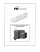
LS Series “Little Still” Instruction Manual Introduction This LS Series solvent distillation system provides safe, on-site reclamation of contaminated solvents. Use of the Little Still can save money and conserve the environment by reducing or eliminating the disposal of these solvents. Quality engineered and manufactured, the Little Still requires minimal operator involvement. When properly installed, operated, and maintained, this equipment can provide years of trouble-free service.
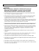
Safety Precautions WARNING: READ THIS MANUAL COMPLETELY BEFORE INSTALLING AND OPERATING THIS EQUIPMENT. FAILURE TO FOLLOW THESE PRECAUTIONS CAN RESULT IN SERIOUS INJURY OR DEATH. Installation location and area must conform to requirements set by National Electric Code Class 1, Division 1, Group D for hazardous locations. Follow National Fire Protection Association guidelines for control of static electricity (NFPA 77, Recommended Practice on Static Electricity).
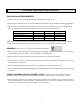
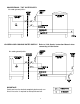
Installation Requirements and Instructions PHYSICAL SPACE REQUIREMENTS: See Safety Precautions for important information regarding the installation area. The unit must be installed on a level concrete pad/floor and protected from the weather and freezing temperatures. Approximate overall dimensions/space requirements are listed below. Additional space is required around and above the equipment for loading and unloading, storage drums, access for maintenance, etc.
SPECIAL ASSEMBLY FOR INSTALLATIONS WITH A JETVAC: When installing a JetVac attachment to a Little Still, the system is installed and assembled in a way that allows the system to operate either with or without the JetVac. Use pipe tape on all threaded connections to prevent vacuum leaks. Set the JetVac to the right of the Still, with approximately 24 inches of space between the units.
ELECTRICAL REQUIREMENTS: CAUTION: A qualified electrician should perform electrical connections. Improper electrical wiring can result in damage to components. See Safety Precautions for important information regarding the electrical connections. Electrical power requirements to the control panel are 240 volts, 1 phase, 50/60 hertz from a protected circuit and earth ground. If the incoming voltage is 208 volts, processing time will increase.
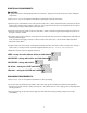
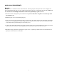
L1 LITTLE COOLER INCOMING POWER (SWITCHED) L2 INCOMING POWER INCOMING POWER L1 L2 L1 L2 A 1L2 JETVAC LS-15E/55E STILL Electrical connections for an LS-15E/55E CUSTOMER SUPPLIED CONTACTOR CC1 L1 CC2 LITTLE COOLER INCOMING POWER L2 B TO “CUSTOMER SUPPLIED” CONTACTOR COIL FOR LITTLE COOLER INCOMING POWER L1 L2 C.C.
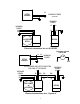
CONDENSER COOLING WATER REQUIREMENTS: WARNING: Improper cooling water supply can result in the accumulation of hazardous vapors (refer to Safety Precautions for ventilation information). CAUTION: Do not allow the cooling water supply to freeze. Damage to components can occur. Do not exceed 85 psi inlet water pressure. Cooling water can be supplied via “tap water” or from a closed-loop cooling system (e.g., a Little Cooler or cooling tower).
QUICK COOL REQUIREMENTS NOTE: The Quick Cool is standard in the LS-15E/15IIE units. The main purpose of the quick cool coil is to rapidly cool down the distillation tank after a cycle is complete, which allows the user to run multiple shifts each day. If the user does not intend to run multiple shifts, FTI recommends not plumbing the quick cool coil. The Little Cooler is designed only for condenser cooling. Do not attach it to the quick-cool coil (use tap water for the quick cool).
CONVENTIONAL “TAP” WATER SUPPY: Use with optional JetVac. ATMOSPHERIC .CLOSED-LOOP COOLING WATER SUPPLY: Refer to Little Cooler Instruction Manual when connecting a Little Cooler. Use with optional JetVac. ATMOSPHERIC IMPORTANT: Quick cool must be drained completely before each run. An air inlet valve is required to drain quick-cool coil.
Instrumentation and Controls LS SERIES STILLS (ALL MODELS): STOP/START - An illuminated push-button switch. Pull to activate the Still, push to terminate all functions. A green light indicates that the Still is operating within the processing cycle. IMPORTANT: The STOP/START push-button switch must be left pushed in the STOP position for a minimum of five (5) seconds before pulling on. This allows the controls to electrically reset themselves. Failure to do so will prevent the heater from operating.
JETVAC ATTACHMENT: STOP/START - An illuminated push-button switch. Pull to ready the JetVac’s operation, push to terminate all JetVac functions. A green light indicates that the JetVac is operating within the processing cycle. IMPORTANT: The STOP/START push-button switch should remain ON (pulled) when wired for automatic operation. In this mode, the Still will automatically turn on and off the JetVac depending on the status of the Still’s operation.
PUSH TO PULL TO STOP START CYCLE TEMP ºF LS-15E/55E CONTROLS COOLING WATER PUSH TO PULL TO STOP START CYCLE TEMP CYCLE TIMER HOURS ºF HEAT VAPOR TEMPERATURE LS-15IIE/55IIE CONTROLS 15 30 PUSH TO PULL TO START STOP 0 VACUUM GAUGE JETVAC CONTROLS 12
13
Start-up and Operation The LS Series equipment requires minimal operator involvement. Once set up and started, the unit can operate virtually unattended until the process is complete. See Safety Precautions before operating this unit. Explanation of each control and setting can be found in Instrumentation and Controls. CAUTION: Only process neutral waste solvents with a pH between 6 and 9.
LS-15IIE/55IIE MODELS: 1. Open the lid and remove any residues from a previous run. Make sure that the inside of the boiling chamber is clean and free of debris. CAUTION: When cleaning, use only plastic or other non-metallic utensils to avoid scratching the boiling chamber when scraping out residues. Scratching the non-stick coating results in permanent damage and voids the warranty. 2. Install a Stilbag or a Stilpan (if used, see Installing a Stilbag).
JETVAC ATTACHMENT: CAUTION: Do not process solvents with boiling points below 200º F with the JetVac. Release of hazardous vapors and damage to the equipment may result. 1. Lift the top panel of the JetVac’s cabinet and prop it open with the supplied prop bar (attached under the top panel). If changing the solvent or cleaning the reservoir, the “old” solvent can be drained through a ball-valve located on the right side of the JetVac’s cabinet. 2.
INSTALLING A STILBAG: WARNING Proper installation of a Stilbag is critical. Improper installation can result in dangerous pressurization of the boiling chamber. Never disable the Stilbag venting system. 1. Unroll the Stilbag and expand it open. Gather the top opening of the Stilbag, trapping air inside to form a “ball”. 2.
~ Maintenance Schedule ~ CAUTION: Always wear eye protection, protective clothing, gloves and an approved respirator when working on or with this unit. Never work on or with this equipment while it is hot. Never open a hot Still. Allow a minimum of two hours or more cool-down time. EACH USE: CLEAN THE BOILING CHAMBER - Remove any waste residues from the boiling chamber and Stilbag venting system. If necessary, gently scrape the sides with an approved scraper (see Common Spare Parts).
SEMI-ANNUALLY OR AS REQUIRED: ADJUST LID CLAMPS - Make sure that all of the Still’s lid clamps hold tightly. Adjust any loose clamps, and replace clamps that appear weak. CLEAN JETVAC PUMP RESERVOIR - If using a JetVac attachment, drain the pump reservoir and clean and remove all dirt and debris. Inspect parts for corrosion, and replace any suspect parts. CLEAN Y-STRAINERS - The Still’s Y-strainer is located inside of its cabinet.
Service and Troubleshooting In the event the Little Still does not appear to operate correctly, use the following tips to diagnose common problems. If these suggestions do not pinpoint the cause of your problem, contact FTI’s toll-free “Tech Service Hotline” between the hours of 8 a.m. to 5 p.m. EST. Tech Service Hotline - 800-888-3743 WARNING: Never electrically trouble shoot or operate this equipment in the hazardous area when electrical components are exposed (e.g.
LS SERIES STILLS: BASIC TROUBLESHOOTING TIPS CONTINUED… PROBLEM: Stilbags break or melt during a cycle or while lifting out residue. POSSIBLE CAUSES: Temperature too hot. The standard temp Stilbags will become brittle if overheated. Try the hi-temp Stilbags. Stilbag used too long. The Stilbag is designed for a maximum of up to 16 hours and for a single use only. Chemical incompatibility. The Stilbags are made of “Nylon 6” and “Nylon 66.” Check compatibility with your solvent supplier.
JETVAC ATTACHMENT TROUBLESHOOTING TIPS: PROBLEM: JetVac will not turn on. POSSIBLE CAUSES: JetVac is improperly wired. Verify the electrical power and connections to the JetVac and Still. When wired for automatic mode, the Still must be operating for the JetVac to operate. Improper cooling water flow to the condenser. If the flow switch in the Still is not engaged, the JetVac will not operate (when wired in automatic mode). PROBLEM: Low vacuum readings. POSSIBLE CAUSES: 1.
Advanced Troubleshooting Tips: LS-15E / LS-55E WARNING: Qualified electrical personnel must perform all electrical tests and work. There is a potential for sparks when the electrical control box is open. The unit must be removed to a location outside the hazardous area before any electrical work can be done on live circuits. PROBLEM: No heat. Green light not on. 1. Verify that cooling water is properly supplied to the condenser.
Advanced Troubleshooting Tips: LS-15E / LS-55E continued… 3. Verify that the K2 relay on the temp board is closing (when unit is turned on) by measuring for voltage between wire IL2 (on the on/off switch) and wire 6 on pin 14 (on temp board). If no voltage is present, K2 may be faulty and the temp board must be replaced. If 240V is present, K2 has closed and it is all right to continue with troubleshooting tips. 4.
Advanced Troubleshooting Tips: LS15IIE I LS55IIE Warning: Qualified electrical personnel must perform all electrical tests/work. There is a potential for sparks when the electrical control box is open. The unit must be removed to a location outside the hazardous area before any electrical work can be done on live circuits. PROBLEM: Only green light comes on / still 1. With the on/off switch in the ON position (pulled out), opening the solenoid valve (sol-1) controls the water flow. If 240 V.A.C.
Advanced Troubleshooting Tips: LS 15IIE I LS55IIE CONTINUED… 6. Verify that power is getting to the temp board. There should be 24 V.D.C. between wires # 3 (pos.) pin 21 on the temp board and wire # 11 (neg.) pin 23 on the temp board. If this is not the case, than the cycle timer could be defective. The timer can be bypassed by jumping a wire between wire #7 pin 2 on TIM-l and wire #3 pin 1 on TIM-I. If this works, then replace the cycle timer. 7.
Appendix SPARE PARTS - MECHANICAL: Part # A100619 A101047 J100634 A100413 J102937 A100431 A101126 A100416 J100205 J100216 M100182 M100188 A100423 A100439 J100221 A100628 A100587 A100444 J100211 J100210 A101436 M100184 M100115 A100445 A100576 M101055 A100438 Description Aspirator, brass, JetVac Aspirator, stainless steel, JetVac Condenser, LS-15 Condenser, LS-15 stainless steel Condenser, LS-55 Condenser, LS-55 stainless steel Discharge hose Discharge hose with sightglass Flame check-valve, JetVac Heat resi
SPARE PARTS - ELECTRICAL: Item # C1 CTRL1 CTRL1 FS1 FS2 FUSE1 FUSE2 LT2 LT3 MOV1 MTR1 PB1/LT1 PB1/LT1 POT1 POT2 PS1 RC1/RC2 SOL1 SOL2 SSR1/SSR2 TC1 Part # J101486 J102795 J102734 J100914 J100913 J102735 J102919 J102736 J102737 J102738 J103298 J100323 J102739 J102139 J102740 J102741 J101699 J100889 J102249 J102742 J101157 Description Contactor Temp control board, LS-15E/55E Temp control board, LS-15IIE/55IIE Flowswitch, LS-55E/55IIE Flowswitch, LS-15E/15IIE Fuse, System II Fuse, System II (600 mA) Indicato
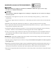
ELECTRICAL SCHEMATIC - LS-JETVAC: C1-2 SOL -2 “NORMALLY OPEN” ELECTRICAL SCHEMATIC - LS-15E/55E: 29
ELECTRICAL SCHEMATIC - LS-15IIE/55IIE: Note: When start button is pulled on, both timers are energized, but timer # 2 does not start timing until timer #1 times out. Note: If using a Little Cooler, connect control wires to the coil of the customer supplied contactor. (refer to the Little Cooler manual).
CHEMICAL REACTION DISCLAIMER The user must exercise primary responsibility in selecting the product's material of construction, which are compatible with the fluid(s) that come(s) in contact with the product. The user may consult Finish Thompson, Inc. (manufacturer) and a manufacturer's representative/distributor agent to seek a recommendation of the product's material of construction that offers the optimum available chemical compatibility.