DB6, 6H, 7, 8, 9, 10 Series Centrifugal Pumps Assembly, Installation and Operation Manual
EU Declaration of Conformity Finish Thompson Inc. hereby declares that the following machine(s) fully comply with the applicable health and safety requirements as specified by the EC Directives listed. The product may not be taken into service until it has been established that the drive motor for the centrifugal pump complies with the provisions of all relevant EC Directives. The complete product complies with the provisions of the EC Directive on machinery safety provided motors carry CE marking.
Table of Contents Important Information - Read Me First Model Number/Serial Number................................................................................................... Important Notice......................................................................................................................... Chemical Reaction Disclaimer................................................................................................... Safety Precautions..............................................
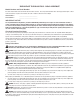
IMPORTANT INFORMATION - READ ME FIRST! Model Number and Serial Number Record the model number and serial number below for future reference. This is important information when ordering replacement parts or when technical assistance is required. The numbers are found on a label located on the motor adapter. MODEL NUMBER = ____________________________ SERIAL NUMBER = ________________________ IMPORTANT NOTICE U.S.
WARNING: The pump and associated components are heavy. Failure to properly support the pump during lifting and movement could result in serious injury or damage to the pump and components. WARNING: Never run pump at less than minimum flow or with the discharge valve closed. This could lead to pump failure. Installation/Operation Precautions CAUTION: This pump should never be operated without liquid in the casing. It is recommended that run dry protection be used.
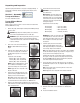
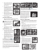
Unpacking and Inspection Unpack the pump and examine for any signs of shipping damage. If any damage is detected, save the packaging and notify the carrier immediately. 6. WARNING: Be careful, magnets will try to attract tools. Section I - Assembly Metric Motors: Secure the drive to the motor shaft using bolt, lock washer and flat washer (items 21, 22, 23). Thread the bolt into the end of the motor shaft (while holding the outer drive to prevent it from turning). See figure 6.
Section II – Installation installed ¼” drain in the impeller housing. See the Drain Installation Section for details. Mounting Motor feet should be securely fastened to a solid foundation. Note: Shims are required for the motor feet on ALL 63, 71 and 80 frame motors and 90 frame B5 motors. · For units in a suction lift system, install appropriate piping in the discharge to allow priming of the pump (DB models are not self- priming).
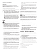
magnet and impeller assembly away from metal chips or particles. Flush Systems CAUTION: Some fluids react with water; use compatible flushing fluid. 1. 1. Turn off the pump. 2. Completely close the suction and discharge valves 3. Connect flushing fluid supply to flush inlet valve. WARNING: The pump must be thoroughly flushed of any hazardous materials and all internal pressure relieved prior to opening the pump. Allow the pump to reach ambient temperatures prior to performing maintenance. 4.
7. Remove the impeller shaft (item 6) from the barrier and check for signs of cracking, chipping, scoring or wear. See figure 15. 8. Remove the barrier (item 7) from the motor adapter (item 11) (make sure the shaft has been removed). If necessary, gently tap on the back side of the barrier with a soft rod (wood, plastic, etc). Inspect the inside and outside of the barrier for signs of rubbing. See figure 16. 9.
5. Install o-ring (item 3) in groove in the barrier. 6. Install impeller shaft (item 6) into barrier by aligning the flats on the shaft with the flats in the barrier. Make sure it is completely seated. See figure 28. Carefully install the impeller/inner drive assembly (items 4A, 4, 5, 5A) by sliding it over the impeller shaft in the barrier. It is normal for the impeller/inner drive to pop up a slight amount due to magnetic forces. See figures 29 and 30. 7. 8. 9.
PART NUMBER EXPLANATION BASE MODEL COMPONENTS 1. Select base model (E.G. DB10P*) 2. If standard components are not suitable, enter symbol(s) of alternative compo nents in any order. Base Model - -__-__-_______ DB10P E-Ff-14 DB10P-E-Ff-14 is a DB10P with EPDM O-ring, fiberglass flanges and 145TC motor. 3. Alternative components - select from chart. *The model number is on the serial number label located on the motor adapter.
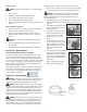
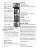
DB 6 - 10 SPARE PARTS DIAGRAM 9
DB 6 - 10 SPARE PARTS LIST Item Qty 1 1 2 1 3 1 4 1 4A 1 5 1 5A 1 6 1 7 1 8 1 DB6/6H/9 Pump Material Polypro PVDF Description Housing w/ Ring NPT threads & standard ceramic ring 106265 BSP threads & standard ceramic ring 106265-2 FRP flanges & standard ceramic ring 106369 Steel flanges & standard ceramic ring 106369-2 Unions & standard ceramic ring 106377 NPT Threads & optional SiC Ring 106346 BSP Threads & optional SiC Ring 106346-2 FRP Flanges & optional SiC Ring 106370 Steel Flang
DB 6 - 10 SPARE PARTS LIST - Cont.
Hardware - All DB6-10 Models Item 15 16 17 18 19 20 Qty 6 6 6 4 4 4 21 1 22 1 23 1 24 4 25 26 4 4 27 4 28 4 29 4 30 4 Description Stainless Steel Titanium J102789 106308 J102282 J103847 105767 105768 105767 105768 J102282 J103847 105770 105771 106314 106312 105765 105770 106315 106313 105766 105771 106322 106320 J100672 J102282 106323 106321 J104203 J103847 106318 106316 105767 105722 106319 106317 105768 105773 J100114 106311 J100115 J104206 J100128 J104207 10
Impeller Assemblies Model Thrust Ring Material Impeller Material #1 #2 #3 #4 #5 #6 #7 #8 #9 3.00 2.75 2.50 3.50 3.25 3.00 2.