OPERATION & iNSTALLATION MANUAL pART nO. J101747, version 3.2, rev.
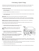
Introduction DESCRIPTION: The Coolant Quick Changer is a time saving members of FTI’s family of coolant handling equipment. This portable unit safely drains and refills automotive engine cooling systems in a portion of the time it takes for conventional methods. When properly operated, this unit induces no air or pressure into the engine’s cooling system. No hose cutting or tee is required - gravity and the engine’s own water pump perform the service.
Safety Precautions WARNING: FAILURE TO FOLLOW THESE PRECAUTIONS CAN RESULT IN SERIOUS INJURY OR DEATH. · Read and understand the operation manual completely before operating this unit. · Always wear proper eye and skin protection when operating and maintaining this equipment. · Hazardous voltages present. Use only with a grounded electrical outlet and grounded extension cords. Do not remove the ground prong from the plug. · Take precautions to keep clothing, hair, hands, hoses, etc.
Assembly INSTALLATION OF SWIVEL CASTERS: Locate the 4 swivel casters and bag of hardware that was shipped in the fill bucket on the top of the unit. Verify that the hardware bag contains 8 bolts, 8 lock-washers, and 8 nuts. Have a helper tilt the unit on its bottom edge to install each caster. Insert the bolt from the top, with the washer and nut on the bottom. Tighten with a 1/2” wrench or socket.
Sequence of Operation The CQC2 is a device designed to perform quick and simple engine coolant changes on automobiles and light trucks. When properly operated, this quick change can be accomplished in as little as ten minutes. The following is the normal sequence of operation for a CQC. Refer to the “Performing A Quick Change” section of this manual for complete instructions before operating your unit. PREPARE FOR THE QUICK CHANGE - A vehicle is pulled into the service area and the CQC is positioned.
Performing A Quick Change Following these procedural guidelines will perform a Quick Change on most vehicles. Due to the variety of automobile, SUV and light truck cooling system designs, slight variations of this procedure may be necessary. PREPARE FOR OPERATION: 1. Pull the vehicle into the service area. Set the vehicle’s heater controls to the highest temperature setting and turn off the heater fan. 2. SHUT OFF THE VEHICLE’S ENGINE and raise the hood. 3.
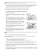
CAUTION: Never allow the evacuation pump to operate without liquid. Running the pump dry will cause premature wear or damage to the pump and is not covered under warranty. 4. Locate the vehicle’s coolant overflow bottle and remove its cap. Insert the plastic wand on RED suction hose into the overflow bottle, turn on the evacuation pump, and remove as much liquid as possible. Turn off the pump and return the RED suction hose to its hose clip. Replace the cap on the overflow bottle.
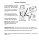
HINT: In some cases, the size difference between the UPPER radiator hose and the step adapter may seem too large. It is OK to tighten down the hose clamp to seal up to a 1/4" gap. A “worm-gear” type clamp tightened with a nut driver works best. 4. Attach the “best fit” flexible hose adapter to the thermostat housing’s inlet and secure it tightly using the sup plied hose clamp. 5. Attach the BLACK drain hose from the CQC2 by inserting its step adapter into the open end of the flexible hose adapter.
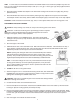
DRAINING THE WASTE COOLANT DRUM: 1. Remove the BLACK hose from the large opening of the waste coolant drum (located in the back of the machine) and place it into a receiving container. 2. Insert the wand from the RED hose into the large opening on the waste coolant drum until it reaches the bottom. 3. Turn ON the evacuation pump (switch located on the front bevel of the unit). 4. Allow the pump to run until all liquid is removed from the waste coolant drum. 5.
MAINTENANCE SCHEDULE (continued) 5. Push the impeller onto the motor shaft and at the same time twist in a clockwise direction. This will bend the blades in the direction for proper operation. 6. Replace the pump’s cover using a new gasket, tightening all screws evenly and snugly. Do not over tighten the screws. Replace the rear panel on the CQC2.
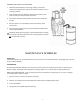
COMMON SPARE PARTS COOLANT QUICK CHANGER2 Item 1 2 3 4 5 6 7 8 9* 10* Description On/off switch Fill bucket Step adapter Ball valve Plastic wand for red hose Red pump hose Black drain hose Green fill hose Pump Impeller Kit Evacuation Pump & Motor Ass’y. * Items are not shown on drawing.
SERVICE 1-800-888-3743 Literature ID No.