
Datasheet

FTLF1421S1XCL 2x10 Pin SFF Product Specification – March 2006 F i n i s a r
Finisar Corporation March, 2006 Rev A Page 6
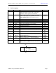
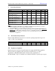
VIII. Analog Diagnostics Functions (T
op
= -10 to 70 °C, V
CC
= 3.00 to 3.60 Volts)
Parameter Symbol Min Typ Max Unit Ref.
Transmitter
Monitor photodiode current monitor Pmon+,
Pmon-
0 Vcc V 1
Laser bias current monitor Bmon+,
Bmon-
0 Vcc V 2
Receiver
Received photocurrent Rpd
0 1 mA 3
Photodiode responsivity R 0.5 0.9 1.0 A/W
Applied voltage at PD pin Vpd
2.4 Vcc V 3
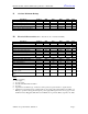
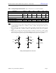
Notes:
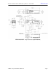
1. Pins 19 and 20 provide an analog voltage output proportional to the monitor photodiode current,
per the following formula: I
BIAS
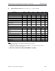
= .V(Pmon+ - Pmon-) / 200Ω. The figure below shows the
equivalent circuit.
2. Pins 17 and 18 provide an analog voltage output proportional to the laser bias current, per the
following formula: I
BIAS
= .V(Bmon+ - Bmon-) / 10Ω. The figure below shows the equivalent
circuit.
3. Pin 1 is used to monitor the received photocurrent. It must be connected to a positive voltage
within the range specified above. The current that flows into this pin is the received photocurrent.
The received power is given by the photocurrent multiplied by the photodiode responsivity.
Vcc
10 Ω
3 KΩ
3 KΩ
Bmon+
Bmon-
Ibias
Vcc
200 Ω
3 KΩ
3 KΩ
Pmon+
Pmon-
Imon
Laser
Monitor
Photodidoe
Vpd
Receiver
Photodidoe
Ipd
Analog monitoring function connections.