
Datasheet
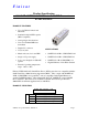

FTLF1421S1XCL 2x10 Pin SFF Product Specification – December 2003 F i n i s a r
Finisar Corporation March, 2006 Rev A Page 2
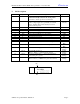
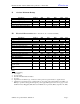
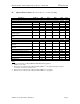
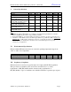
I. Pin Descriptions
Pin Symbol Name/Description Logic Family
MS MS
Mounting Studs for mechanical attachment. Chassis
ground is internally isolated from circuit ground.
Connection to chassis ground is recommended.
NA
1 PD Receiver Power Monitor. This pin must be connected to a
positive voltage supply (Vcc), preferably via a small
resistor. Supplies photocurrent and may be used to
monitor received power.
Analog
Current
2,3,6 V
EER
Receiver Ground (Common with Transmitter Ground) NA
4,5 NC Not Connected.
7 V
CCR
Receiver Power Supply NA
8 SD Signal Detect. Logic 1 indicates normal operation. LVTTL
9 RD-
Receiver Inverted DATA out. AC Coupled CML
10 RD+ Receiver Non-inverted DATA out. AC Coupled CML
11 V
CCT
Transmitter Power Supply NA
12,16 V
EET
Transmitter Ground (Common with Receiver Ground) NA
13 T
DIS
Transmitter Disable LVTTL
14 TD+ Transmitter Non-Inverted DATA in. AC Coupled. CML
ECL
15 TD-
Transmitter Inverted DATA in. AC Coupled. CML
ECL
17 Bmon- Laser Bias Monitoring (-). Analog
Voltage
18 Bmon+ Laser Bias Monitoring (+)
.(Bmon+ - Bmon-) = 10Ω x laser bias current.
Analog
Voltage
19 Pmon- Laser Power Monitoring (-). Current implementation
connects this pin to ground
Analog
Voltage
20 Pmon+ Laser Power Monitoring (+)
.(Pmon+ - Pmon-) = 200Ω x mon. photodiode current.
Analog
Voltage
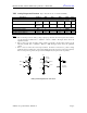
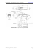
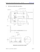
TOP VIEW
6 7 8 9 10
MS
MS
1 2 3 4 5
15 14 13 12 11
20 19 18 17 16