Installer Guide
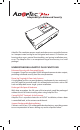
Adaptability to Enhanced Security AdapTec Plus combines power supply and door access controller features in a compact metal casing for an encrypted and secure I/O function, enhancing door access control functionalities and easing installation processes.
Emergency Alerts with Siren Compatible with an NC siren type with a maximum of 0.5A load for emergency event e.g if the terminal is being illegally dismantled. Seamless Integration with FingerTec Terminals Mix and match the FingerTec terminals via AdapTec Plus for a cost effective access control system suitable for small and medium sized offices.
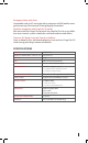
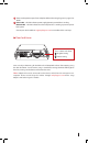
UNDERSTANDING THE DESIGN AdapTec Plus consists of 2 main modules and a timer: 1 2 3 1 Power supply/power input module 2 Access control/power output module 3 Door lock timer Power supply/power input module 1 2 1 This portion is to be connected to power source with AC110~240V. AC current will be supplied into this side and a DC 12V 3A current will be generated as output. 2 These two cables, -V and +V are default and are connected to the inner part of AdapTec.
2 These are the power outputs from AdapTec. Refer to the wiring diagrams in page 3, for details. 3 Power LED – a lit LED indicates power supply/power input module is working. EM lock LED– a lit LED indicates that the AdapTec Plus is working to power up door lock system. Contact your local reseller or support@fingertec.com in case either LED is not lit up.
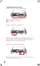
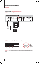
WIRING DIAGRAMS AC900 FUNCTION • Time Attendance Only STEP 1 • Connection Points Access Control/Power Output Module To Battery - + Tamper Siren Switch Output Input EM 12V Output Voltage 12V 0V AdapTec Plus Siren Door Accept Exit Wiegand Input GND WD0 WD1 GND PWR DC 12V Rechargeable Backup Battery Connection Points STEP 2 • Connect AdapTec Plus to a Power Source Power Supply/Power Input Module L N E R B G -V AC110~240V L - Live N - Neutral E - Earth R Red B Blue G Green STEP 3 • Turn on
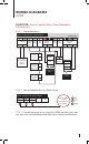
WIRING DIAGRAMS AC900 FUNCTION • Access Control Only or Time Attendance & Door Access STEP 1 • Connection Points Access Control/Power Output Module To Battery - Tamper Siren Switch Output Input + DC 12V Rechargeable Backup Battery EM 12V EM + Lock - AdapTec Plus Output Voltage 12V 0V Siren Door Accept Exit Wiegand Input GND WD0 WD1 GND PWR Release Button Emergency 2 Break Glass (NC) 3 GND WD0 WD1 Connection Points Connection Points ON-OFF C Key Switch (NC) D STEP 2 • Connect AdapTec Plus
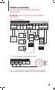
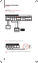
WIRING DIAGRAMS R2, i-Kiosk100, i-Kiosk100 Plus, Q2i, Kadex and m-Kadex FUNCTION • Time Attendance Only STEP 1 • Connection Points Access Control/Power Output Module To Battery - + Tamper Siren Switch Output Input EM 12V Output Voltage 12V 0V AdapTec Plus Siren Door Accept Exit Wiegand Input GND WD0 WD1 GND +12V DC 12V Rechargeable Backup Battery Connection Points STEP 2 • Connect AdapTec Plus to a Power Source Power Supply/Power Input Module L N E R B G -V +V AC110~240V L - Live N - Neu
WIRING DIAGRAMS R2, i-Kiosk100, i-Kiosk100 Plus, Q2i, Kadex and m-Kadex FUNCTION • Access Control Only or Time Attendance & Door Access STEP 1 • Connection Points Access Control/Power Output Module To Battery - Tamper Siren Switch Output Input + DC 12V Rechargeable Backup Battery EM 12V EM + Lock - AdapTec Plus Output Voltage 12V 0V Siren Door Accept Exit Wiegand Input GND WD0 WD1 GND +12V Release Button Emergency 2 Break Glass (NC) 3 GND WD0 WD1 Connection Points Connection Points ON-OFF
WIRING DIAGRAMS Face ID 2 FUNCTION • Time Attendance Only STEP 1 • Connection points Access Control/Power Output Module To Battery - Tamper Siren Switch Output Input + EM 12V AdapTec Plus Output Voltage 12V 0V Siren Door Accept Exit Wiegand Input GND WD0 WD1 +12V GND DC 12V Rechargeable Backup Battery Connection Points STEP 2 • Connect AdapTec Plus to a power source Power Supply/Power Input Module L N E R B G -V +V AC110~240V L - Live N - Neutral E - Earth R Red B Blue G Green STEP 3
WIRING DIAGRAMS Face ID 2 FUNCTION • Access Control Only or Time Attendance & Door Access STEP 1 • Connection points Access Control/Power Output Module + - Siren Door Accept Exit Wiegand Input GND WD0 WD1 Release Button ON-OFF C Key Switch (NC) D GND Emergency 2 Break Glass (NC) 3 +12V DC 12V Rechargeable Backup Battery EM Lock Output Voltage 12V 0V WD1 + EM 12V SGND - Tamper Siren Switch Output Input WD0 To Battery AdapTec Plus Connection Points STEP 2 • Connect AdapTec Plus to a powe
CONNECTING ADAPTEC PLUS TO AN ALARM SIREN For all FingerTec door access control models, there is a security button behind the terminal. During normal operation, the security button is compressed and once the terminal is dismantled, the button will be released and “System broken” message will appear onscreen. During the release of the button, the terminal will output an alarm signal. Nonetheless, no alarm sound will be emitted if the terminal is not equipped with a preinstalled siren.
FUNCTION • AC900 For AC900, you will need to connect AC900, alarm siren and AdapTec Plus as below.
UNDERSTANDING ADAPTEC INSTALLATION FOR • Wooden Door The diagrams below only highlight the use of an EM lock during installation. You may opt to use a dropbolt/deadbolt/door strike instead. Please consult a qualified technician/installer before proceeding with the installation. 1 WOODEN DOOR WALL WALL 1 2 Back Steel Plate 2 Tighten the 4 screws to fix the Back Plate on the wall. Screws 4 feet / 1.2 meter (recommended) 3 3 Install the keyswitch as per instructions given in the box.
4 1 12V 3A DC Power 2 2 Output AC110/240V Power Input 33 1 Note: Refer to AdapTec user guide for wiring diagrams. 1 Computer/ Network Hub/ Network Switch To FingerTec®Series 2 AdapTec Plus ABOVE CEILING 3 12V Rechargeable Battery CEILING BELOW CEILING Note: It is recommended to place 1 , 2 and 3 out of sight, either above a ceiling or wall-mounted. 5 CEILING Emergency Break Glass Emergency Break Glass Push Button 4 feet / 1.
UNDERSTANDING ADAPTEC INSTALLATION FOR • Glass Door The diagrams below only highlight the use of an EM lock during installation. You may opt to use a dropbolt/deadbolt/door strike instead. Please consult a qualified technician/installer before proceeding with the installation. 1 GLASS DOOR WALL WALL 1 2 2 Tighten the 4 screws to fix the Back Plate on the wall. Back Steel Plate Screws 4 feet / 1.2 meter (recommended) 3 Install the keyswitch as per instructions given in the box.
4 1 12V 3A DC Power 2 2 Output AC110/240V Power Input 33 1 1 Computer/ Network Hub/ Network Switch To FingerTec®Series ABOVE CEILING 2 AdapTec Plus Note: Refer to AdapTec user guide for wiring diagrams. 3 12V Rechargeable Battery CEILING BELOW CEILING Note: It is recommended to place 1 , 2 and 3 out of sight, either above a ceiling or wall-mounted. 5 CEILING Emergency Break Glass and Push Button should Emergency Break Glass be installed indoors.
FINGERTEC EXCLUSIVE ACCESSORIES For more accessories go to accessory.fingertec.com.
OTHER RESOURCES Information About FingerTec TO LEARN ABOUT GO TO? Company and the products www.fingertec.com The latest updates Facebook Fan Page: FingerTec Worldwide Twitter: FingerTec Worldwide To subscribe for FingerTec Newsletter: www.fingertec.com/subscribe-R/newsletter.html Technical Tips and Latest Product Updates and Upgrades user.fingertec.com Email info@fingertec.com (Sales) support@fingertec.com (Technical) Register for Warranty www.fingertec.com/GPW/warranty.
MOUNTING AN ADAPTEC PLUS ONTO A WALL 1 Remove the L-shape piece from the AdapTec plus Find an L-shape piece at the top right of an AdapTec Plus. This piece is attached to the AdapTec Plus with 2 screws. 2 Install the piece to the AdapTec Plus Attach the L-shape to the AdapTec Plus as shown and tighten the screws. 4 After removing the piece, you will have one L-shape piece and 2 screws. 3 The other 2 holes at the bottom Open the cap, look for the part shown in the diagram and you will see 2 holes.