
Datasheet


20
7P Series - Surge Protection Device (SPD)
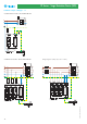
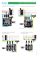
Protection against SPD’s short circuits is provided by the overcurrent
protective devices (fuses type gL/gG) recomended.
If the overcurrent protective devices F1 (which are part of the
installation) have a rating smaller than or equal to the maximum
recommended rating for the overcurrent protective devices F2 (back up
fuse), then F2 can be omitted.
7P.0X:
If F1 > 250 A, then F2 = 250 A
If F1<= 250 A, F2 can be omitted
7P.1X, 7P.2X:
If F1 > 160 A, then F2 = 160 A
If F1<= 160 A, F2 can be omitted
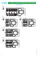
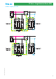
Coordination of SPD
Optimal protection from surges requires cascaded coordinated SPDs.
Coordination has the purpose of splitting the energy associated with
voltage across the SPDs and it is achieved by introducing an
impedance between the SPDs, or alternatively, by connecting them
using wires having the minimum length indicated in the figures
below, in order to use the impedance of its own conductor.
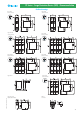
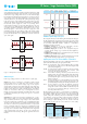
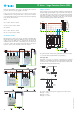
V-shape connection
Using a V-shaped connection eliminates transferring downstream the
inductive voltage generated by the surge current in the connecting wire
to the SPD. This increases the protection to the system and equipment
downstream. A limitation of this connection is that the nominal current
for the downstream system is limited to 125A, which is the maximum
current permitted through the double SPD terminals.
For systems where the rated current is greater than 125 A, it is necessary
to connect the SPD in parallel with the equipment (E/I).
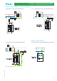
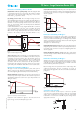
Connecting cable
Depending on the type of connection, serial (V-shape) or parallel
(T-shape), ensure that both the maximum cable lengths and minimum
cross section of the connecting wires are respected in accordance with
the information below (IEC 60634-5-534):
The section of the connecting wires (copper) must not be less than:
SPD Type 1: 6 mm
2
SPD Type 2: 4 mm
2
SPD Type 3: 1.5 mm
2
125 A
125 A
125 A
XII-2012, www.findernet.com