
Datasheet


9
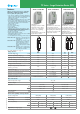
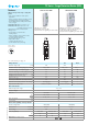
Example: 7P series, surge protection device, Type 2, single phase (Uc = 275 V), 1 varistor + 1 encapsulated spark gap, with remote status
signalling contact, In = 20 kA
Nominal discharge current
100 = 100 kA (I
imp
Type 1) only for 7P.09,
N-PE GDT for 7P.04
050 = 50 kA (I
imp
Type 1 N-PE GDT for 7P.02)
025 = 25 kA (I
imp
Type 1+2)
020 = 20 kA (I
n
Type 2)
012 = 12.5 kA (I
imp
Type 1+2)
003 = 3 kA (In @ U
oc
only for 7P.32)
Remote status signalling contact
1 = Built-in remote status signalling contact
2 = Acoustic fault signalling
6 = Upside down screw position
Series
Type
0 = Combined type 1 + 2 arresters
high discharge capability
1 = Type 1+2 “Low U
p
performance” surge arresters
2 = Type 2 surge arresters
3 = Type 3 surge arresters
Circuit
1 = Single phase (1 varistor)
2 = Single phase (1 varistor + 1 spark-gap)
3 = Three-phase (3 varistors)
4 = Three-phase (3 varistors + 1 spark-gap)
5 = Three-phase (4 varistors)
6 = 2 varistors + 1 spark-gap
9 = N-PE spark-gap for three phase system
0 = Spare module
Supply version
1 = N+PE connection
(only for single spark gap replaceable module and 7P.09)
8 = AC (50/60 Hz)
9 = DC (PV application)
Supply voltage
000 = 1,000 V DC Max (or N+PE connection for spark gap modules)
700 = 700 V DC Max
420 = 420 V DC Max
275 = 275 V Max for SPD Type 1+2 “Low U
p
”, Type 2 (U
c
) (for U
N
= 230-240 V AC) and Type 3
260 = 260 V Max (U
c
) for SPD Type 1+ 2 (for U
N
= 230-240 V AC)
255 = 255 V Max (U
c
) for SPD Type 1, N+PE (7P.09)
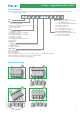
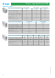
2 2 1 08 2 0
Ordering information
... .
2757P
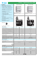
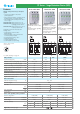
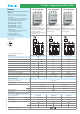
7P Series - Surge Protection Device (SPD)
Upside down mounting
1
2
3 4
XII-2012, www.findernet.com