
Datasheet


2
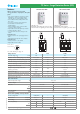
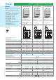
7P.03.8.260.1025 7P.04.8.260.1025 7P.05.8.260.1025
• SPD Type 1+2
• 3 x combination of varistor
and encapsulated spark gap
+ 1 encapsulated spark gap
• Visual fault and remote contact
fault signalling varistor/GDT status,
N-PE GDT presence
• Upside down mounting position
• Replaceable modules
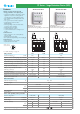
• SPD Type 1+2
• 3 x combination of varistor
and encapsulated spark gap
• Visual fault and remote contact
fault signalling varistor/GDT status
• Upside down mounting position
• Replaceable modules
• SPD Type 1+2
• 4 x combination of varistor
and encapsulated spark gap
• Visual fault and remote contact
fault signalling varistor/GDT status
• Upside down mounting position
• Replaceable modules
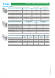
SPD specification
Nominal voltage (U
N
)V AC
Maximum operating voltage (U
C
)V AC
Lightning impulse current (10/350 µs) (I
imp
)kA
Nominal discharge current (8/20 µs) (I
n
)kA
Maximum discharge current (8/20 s) (I
max
)kA
Voltage protection level (U
P
)kV
Ability to independently switch off the
following current (I
fi
)A
Response time (t
a
)ns
Short-circuit proof at maximum overcurrent protection kA
rms
Maximum overcurrent protection
Maximum overcurrent protection for serial connection
Replacement modules code
Other technical data
Ambient temperature range °C
Protection degree
Wire size
mm
2
AWG
Wire strip length mm
Screw torque Nm
Remote status signalling contact specification
Contact configuration
Rated current A AC/DC
Rated voltage V AC/DC
Wire size (07P.01)
mm
2
AWG
Approvals (according to type)
Features
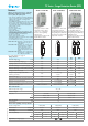
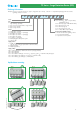
SPD Type 1+2 Surge arrester range - three phase
high discharge capability and without following
current - system (230/400 V)
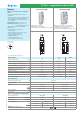
• Surge arresters, suitable for low-voltage applications,
to protect equipment against overvoltage by direct
lightning strike, induction overvoltage and
switching overvoltage
•
To be installed at the boundary of LPZ 0 - LPZ 1 zones or higher
• Versions with combined high energy varistor
block and heavy duty encapsulated spark gap (GDT)
which eliminates leakage current and ensures
high discharge current
• No follow current
• Very low residual voltage
• Low U
p
voltage
• Replaceable modules
• Upside down mounting possible (thanks to dual
terminal markings and new restraint system for
the replaceable module that permits its inversion)
• Visual fault signalling: Healty/Replace
• Double screw terminal
• Remote status signalling contact:
Healty/Replace/Presence. Connector 07P.01 included
• According to EN 61 643-11
• 35 mm rail EN 60715 mounting, 36mm each pole
7P.03.8.260.1025 SPD Type 1+2 for three phase
system without Neutral
(PEN conductor). Varistor + GDT
protection L1, L2, L3-PEN
7P.04.8.260.1025 SPD Type 1+2 for three phase
system with Neutral. Varistor +
GDT protection L1, L2, L3-N +
spark gap protection N-PE
7P.05.8.260.1025 SPD Type 1+2 for three phase
system with Neutral. Varistor +
GDT protection L1,
L2, L3-N +
varistor + GDT protection N-PE
7P Series - Surge Protection Device (SPD)
L-PEN L-N N-PE L, N-PE
230 230 — 230
260 260 255 260
25 25 100 25
30 30 100 30
60 60 100 60
1.5 1.5 1.5 1.5
No following No following
100
No following
current current current
100 100 100 100
50 50 — 50
250 A gL/gG 250 A gL/gG — 250 A gL/gG
125 A gL/gG 125 A gL/gG — 125 A gL/gG
7P.00.8.260.0025
7P.00.8.260.0025 7P.00.1.000.0100
7P.00.8.260.0025
–40...+80
IP20
solid cable stranded cable
1X2.5...1x50 1X2.5...1x35
1X13...1x1 1X13...1x2
11
4
1 CO (SPDT) 1 CO (SPDT) 1 CO (SPDT)
0.5 - 0.1 0.5 - 0.1 0.5 - 0.1
250 250 250
solid cable stranded cable solid cable stranded cable solid cable stranded cable
1.5 1.5 1.5 1.5 1.5 1.5
16 16 16 16 16 16
For outline drawing see page 11, 12
XII-2012, www.findernet.com