
Quick Installation Guide

7
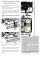
8. Connecting the alarm
contact and the remote
control
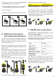
Characteristics and dimensioning of the
cable for alarm and remote control contact:
The characteristics that the cable must
possess are indicated in the following table:
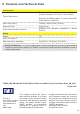
AWG / mm²
Operational
voltage
Operational
temperature
24 - 16
0.2 - 1.5
≥300 V -20...+60 °C
Using the Alarm terminal
Connections to the configurable ALARM relay
are through the terminals (04). This allows
connection to external devices to signal fault
conditions or load control. The operation
mode can be selected in the "INVERTER>
SETTINGS> Alarm" menu.
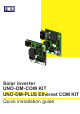
K1
J2
J3
1
J4
MP1
-T/R
RTN
RTN
RS485REM
+T/R
+R
120
TERM.
ON
OFF
DRM0
N.C.
N.O.
ALARM
C
UNO-DM-COM KIT
04
The operation modes that can be selected:
Production, Alarm, Alarm Configurable,
Crepuscolar, Alarm Configurable Latch, Alarm
Configurable ext, GoGo relè (Auto), GoGo
relè (Remote). Refer to the product manual for
further details on the operation modes of the
Alarm terminal.
ATTENTION – A The ALARM contact
can only be used with systems that
include additional safety insulation
(supplementary insulation in relation to
the DC input voltage).
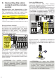
Using the REM terminal
The REM terminal (06), when properly
configured, allows the use of the “Remote ON /
OFF” or the “DRM0” functions.
The inverter can be disconnected from the grid
remotely using the REMOTE ON/OFF function.
This function is enabled in the “INVERTER
> SETTINGS > Remote ON/OFF” menu. To
use purely as a REMOTE ON/OFF, the DRM0
jumper (03) must be set to "OFF".
K1
J2
J3
1
J4
MP1
-T/R
RTN
RTN
RS485REM
+T/R
+R
120
TERM.
ON
OFF
DRM0
N.C.
N.O.
ALARM
C
UNO-DM-COM KIT
06
Where required, it is possible to activate the
DRM0 function by configuring the Jumper for
the activation of the DRM0 function (03) in the
“ON” position.
DRM0
ON
OFF
03
ATTENTION – A In case the DRM0
function is enabled if the proper connection
of the REM terminal is not made, the
inverter will remain disconnected.
Refer to the product manual for further
information on the DRM0 function.