
Quick Installation Guide

6
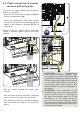
To connect the wires to the Alarm (04), RS485
and REM (06) connector terminals:
1) With a flathead screwdriver, hold the button
corresponding to the contact to be wired.
2) Insert the cable.
3) Release the button and check the cable seal.
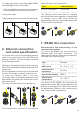
6. Ethernet connection
and cable specification
If it’s required to use a pre-assembled ethernet
cable to be connected to the UNO-DM-PLUS
Ethernet COM KIT, it will be necessary to make
the following operation:
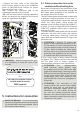
A) Remove the gasket with three holes from the
M25 cable gland disassembling the thread-lock
sealing nut.
B) Cut the gasket from the edge to an hole with
a cutter or a scissor as shown in the pictures.
C) Insert the Ethernet cable in the hole
previously cutted of the gasket with three holes
and assebly the gasket with three holes on the
M25 cable gland.
D) Firmly screw the thread-lock sealing nut.
A B C D
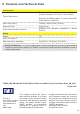
The characteristics required for the ethernet
cable are listed in the table below:
Type Cable diameter
CAT 5E or greather 6 mm max.
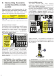
The ethernet cable must also be wrapped
around the EMI ferrite supplied in the package
(1 winding); such a EMI ferrite should be
appropriately placed on the inside bottom side
of the inverter compartment.
1 2 3
7. RS485 line connection
Characteristics and dimensioning of the
communication cables
To connect the RS485 line, you must use a
shielded cable with three conductors. The
characteristics that the cable must possess are
indicated in the following table:
Type Shielded
AWG (mm²) 24 - 16 (0.2 - 1.5)
Characteristic
impedance
120 Ohm
Operational voltage ≥300 V
Operational
temperature
-20...+60 °C
The wiring of the RS485 line must also be
wrapped around the EMI ferrite supplied in the
package (1 winding); such a EMI ferrite should
be appropriately placed on the inside bottom
side of the inverter compartment.
1 2 3