
Quick Installation Guide

4
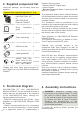
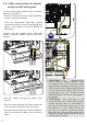
- Remove the front cover of the UNO-DM-
PLUS inverter (Refer to the quick installation
guide of UNO-DM-PLUS inverter for proper
removal of the front cover)
-(A): Connect the connector (01) to the
counterpart present on the inverter
-(B): Use the tower with the spring supplied to
secure the board to the chassis of the inverter
using the appropriate hole (05)
WARNING – B Before turning on the unit,
it is mandatory to close the cover of the
inverter.
OR
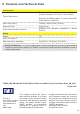
5. Instructions for connection
READ THE MANUAL – E For more information
about the configuration and use of the terminal
for communication and control signals, refer to
the inverter product manual.
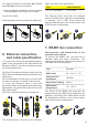
5.1 Cable connection in inverter
versions without wiring box
Each cable connected to the connectors of the
accessory board must be passed through the
M25 cable gland (supplied) to be installed on
the bottom part of the inverter.
The M25 cable gland (that accepts a cable with
a diameter ranging between 10 mm and 17
mm) and a gasket with two holes to be inserted
inside the cable gland, which allows the
passage of two (in case of UNO-DM-COM KIT)
or three (in case of UNO-DM-PLUS Ethernet
COM KIT) separate cables with a maximum
diameter of 6 mm.
To install the M25 cable gland remove the M25
protection cap from the inverter and replace
it with the cable gland, fastening it with the
same M25 lock nut and the same O-ring of the
protection cap.
ATTENTION – A Caution! To ensure the
degree of environmental protection IP65,
it is necessary to fix the cable gland to the
inverter chassis with a minimum torque of
7.5 Nm. When installing the cable gland
M25 use the O-ring removed from the M25
protection cap (installed into the inverter)
to mantain the IP65 protection level!
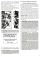
If only a single cable is being passed through
the gasket, the TGM613 cap must be inserted
into the spare hole to ensure degree of
environmental protection (see figure below).
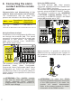
ATTENTION – A
The communication
cable (ethernet and/or RS485) must
be wrapped around the EMI ferrite (08)
supplied in the package (1 winding); such a
EMI ferrite should be appropriately placed
on the inside bottom side of the inverter
compartment (see side illustration and
ethernet/RS485 connection paragraph in
this guide).
ATTENTION – A The connection of the
communication and control signal cables
should be done with no over-length of
the above mentioned cables (as in the
illustration). i.e. the cables should be
run over the internal protective sheet.
Moreover the communication and control
signal connection cables should not be in
contact witn AC cables.
A
B
A
B
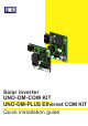
UNO-DM-PLUS Ethernet COM KIT
installed inside the inverter,
DRM0 supported