
Quick Installation Guide

3
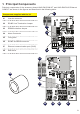
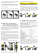
2. Supplied component list
Inside the package, the following items are
supplied
Components supplied with the kit Q.ty
Accessory Board
UNO-DM-COM KIT
or
UNO-DM-PLUS
Ethernet COM KIT
1
Quick installation
guide
1
Tower with spring 1
EMI ferrite (08) 2
Cable gland M25 1
Gasket with two/
three* holes for the
service cable gland
M25 + cap TGM613
1+1 or 2
*Gasket with three holes and two pieces of
cap TGM613 only on UNO-DM-PLUS Ethernet
COM KIT
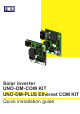
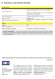
3. Functional diagram
UNO-DM-COM KIT and UNO-DM-PLUS
Ethernet COM KIT are the optional accessory
boards that can be integrated in the inverters
of the UNO-DM-PLUS family offering the
following additional functions:
- Ethernet communication port (RJ45) (Only
available on UNO-DM-PLUS Ethernet COM
KIT board)
- RS485 communication port for connecting
either an external monitoring / control system
or a supported meter for implementing a
Dynamic feed-in control.
- Remote ON/OFF Digital Input.
- Alarm Contact.
- Demand Response Mode 0 required by AS/
NZS 4777.2:2015
The expansion board can be inserted directly
into the dedicated connector inside the inverter
and can also be easily added to a previously
installed inverter.
The installation must be performed by an
installer or by a trained technician after reading
the instructions given in this guide.
The board is directly powered by the inverter
and provides the required safety isolation from
the primary side of the inverter.
(Only available on UNO-DM-PLUS Ethernet
COM KIT board)
The Ethernet connectivity is based on Zero-
Conf IP protocol with DHCP client.
Ethernet port provides access to the
integrat-ed Web User Interface as well as
already pos-sible with the WiFi communication
channel simultaneously.
Both RS-485 and Ethernet communication
ports can be set for enabling communication
over either Modbus (RTU and TCP respec-
tively) protocol Sunspec complaint or proprie-
tary communication protocol named Aurora
Protocol.
Only one client at a time is allowed commis-
sioning the inverter or reading and/or writing
the inverter’s registers.
Available supported Sunspec modes and reg-
ister map are published.
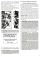
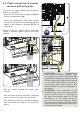
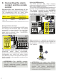
4. Assembly instructions
WARNING – B Hazardous voltages may
be present on accessory board. To avoid
the risks for electric shock, the access
to the internal zones of the inverter must
be carried out after at least 5 minutes
following the disconnection of the
equipment from the network and from the
photovoltaic generator.
To install the accesory board, perform the
following steps: