Solar inverter UNO-DM-COM KIT UNO-DM-PLUS Ethernet COM KIT Quick installation guide
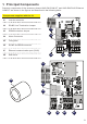
1. Principal Components Principal components of the accessory board UNO-DM-COM KIT and UNO-DM-PLUS Ethernet COM KIT are shown in the figures and described in the following table: 01 02 RS485 Line Termination Jumper 03 DRM0 Activation Jumper 04 Alarm Connector 05 Fixing hole 06 RS485 and REM connector 07 Ethernet communication port (RJ45) 08 EMI ferrite 02 K1 03 J3 1 ON OFF ALARM 04 MP1 05 J2 J4 DRM0 120 TERM. +R RTN RTN +T/R -T/R Inverter connector C N.C. N.O.
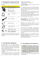
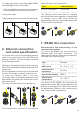
2. Supplied component list Inside the package, the following items are supplied Components supplied with the kit Q.ty Accessory Board UNO-DM-COM KIT or 1 UNO-DM-PLUS Ethernet COM KIT Quick guide installation 1 Tower with spring 1 EMI ferrite (08) 2 Cable gland M25 1 Gasket with two/ three* holes for the 1+1 or 2 service cable gland M25 + cap TGM613 *Gasket with three holes and two pieces of cap TGM613 only on UNO-DM-PLUS Ethernet COM KIT 3.
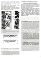
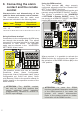
- Remove the front cover of the UNO-DMPLUS inverter (Refer to the quick installation guide of UNO-DM-PLUS inverter for proper removal of the front cover) -(A): Connect the connector (01) to the counterpart present on the inverter -(B): Use the tower with the spring supplied to secure the board to the chassis of the inverter using the appropriate hole (05) A B B B WARNING – Before turning on the unit, it is mandatory to close the cover of the inverter.
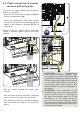
.2 Cable connection in inverter versions with wiring box To connect the signal cables to the accessory board is necessary to: - R emove both front covers (wiring box (05) and inverter compartment (04)) - I nsert the appropriate water-tight conduit connector on signal conduit opening (15) and tighten to the chassis to maintain NEMA 4X compliance. Conduit must be sealed using water-tight fittings to maintain NEMA Type 4X enclosure integrity.
To connect the wires to the Alarm (04), RS485 and REM (06) connector terminals: 1) W ith a flathead screwdriver, hold the button corresponding to the contact to be wired. 2) I nsert the cable. 3) R elease the button and check the cable seal. cable are listed in the table below: Type Cable diameter CAT 5E or greather 6 mm max.
UNO-DM-COM KIT Characteristics and dimensioning of the cable for alarm and remote control contact: The characteristics that the cable must possess are indicated in the following table: AWG / mm² Operational Operational voltage temperature 24 - 16 0.2 - 1.5 ≥300 V J4 DRM0 120 TERM. +R RTN RTN +T/R -T/R C N.C. N.O. MP1 06 J2 REM RS485 J4 Where required, it is possible to activate the DRM0 function by configuring the Jumper for the activation of the DRM0 function (03) in the “ON” position.
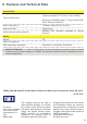
9. Features and Technical Data Connections Type of connectors Connectors with spring (Cables accepted: 0.2-1.5 mm² / 24-16 AWG) Ethernet 10/100Mbits base –T (only on UNO-DMPLUS Ethernet COM KIT) Alarm relay rating Floating contact (230V, 1A max.