TS06A, LPG Anodized Aluminum, Electronic Dispenser Meter Installation, Operation & TS06AS86 with thermo well Parts Manual Non-Compensated Assembly No., With Thermo Well Single __ TS06AS83 __ TS06AS86 Twin __ TS06AS84 __ TS06AS88 for register __ TS06AE83 __ TS06AE86 with EMR³ __ TS06AE93 __ TS06AE96 with ELNC __ TS06AE71 __ TS06AE72 __ TS06AE73 S/No.
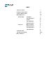
INDEX Safety Procedures 3 Installation & Operations Torque & Wrench Chart Meter Maintenance Disassembly Parts List: 4-6 5 7-10 Flow Meter 9 Inlet Check Valve 10 Strainer 10 Vapor Eliminator 10 Differential Valve 10 Meter & Strainer 13 Differential Valve 11 Inlet Check Valve 11 Vapor Eliminator 11 Troubleshooting 14 SCL (Pulser Assembly) 15-16 Meter calibration 16
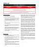
SAFETY PROCEDURES This manual provides warnings and procedures that are intended to inform the owner/operator of the hazards present when using the Tuthill Transfer Systems, TUTHILL meters and other products. The reading of these warnings and the avoidance of such hazards is strictly in the hands of the owner/operator of the equipment. Neglect of that responsibility is not within the control of the manufacturer of the flow meter.
Installation & Operation Installation: In critical installation, block valves and by-pass lines are recommended. This allows the meter to be serviced without interruption of flow in a critical process application. Before Start-up of the Meter, make certain: The meter is properly mounted, secured and piped All shipping plugs are removed and lines are clean of all debris.
Installation & Operation continued Every meter should be calibrated under actual service and installation conditions. Follow your local Weights and Measures recommendations. Provide a means of conveniently diverting liquid for calibration purposes. Give careful attention to your system’s pumping equipment and piping because of their influence on the liquid being measured as it enters the meter assembly. Systems should be made free of conditions that cause or introduce entrained air or vapor.
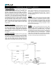
Installation & Operation continued Where the TS06A is used in a commercial or retail LPG dispenser, the flow meter will be shown in dispenser manufacturer wiring diagram. In wiring diagrams on these 2 pages, we show the flow meter used with registers available through Tuthill. it can of course also be used with many other registers.
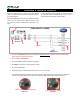
Installation & Operation continued TS06A with SCL & ER9044 (ELNC-1141) register, AC powered through EL2057 ELPS-2057 AC power supply & barrier EL0300-5 SCL inside flow meter front cover 1. This drawing does not guarantee compliance for intrinsically safe apparatus. Refer to CD1000, CD1001 and State & National electrical codes. 2. Terminate shields only at J1-4. 3. Cable lengths are limited by entity parameters.
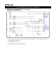
Installation & Operation continued TS06A with SCL & ER-9044-2 (ELNC-1141E) register, with Backlight Display & 10:1 Pulse, AC powered through EL2057 1. This drawing does not guarantee compliance for intrinsically safe apparatus. Refer to CD1000, CD1001 andState & National electrical codes. 2. Cable lengths are limited by entity parameters. 3. ELPS output option: Install U1, R3, TB6.
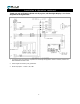
Installation & Operation continued pass lines. Theory of Operation; The TUTHILL meters LPG metering system combines an oval gear positive displacement meter, differential valve, strainer and vapor eliminator in one assembly. The differential valve incorporates a piston type construction with the piston moving away from its seat when at least 15 PSI pressure (above product vapor pressure) is maintained at the meter outlet.
Flow Meter Maintenance Danger!! Danger!! Danger!! Relieve all internal pressure before servicing. Line pressure must be 0.0 PSI Serious injury or death from fire or explosion could result from maintenance of an improperly de-pressurized and evacuated system. Preparing for Service: Close the belly valve of the supply tank. Close the valve on the vapor return line. Close the manual valve in the supply line on eh inlet side of the meter.
Flow Meter Maintenance 11
Flow Meter Maintenance Danger!! Danger!! Danger!! Relieve all internal pressure before servicing. Line pressure must be 0.0 PSI Serious injury or death form fire or explosion could result from maintenance of an Meter Disassembly: If your meter is equipped with an electronic register, remove the register and register housing assembly. Disconnect the outlet flange (30) and the vapor tube connecting the differential valve and the vapor return line.
Flow Meter Maintenance Inlet Check Valve Service: (Optional component) Inspect the slide valve. Remove and build–up of salts or dirt which may cause the valve to stick. The valve should slide freely without any signs of sticking. There should be no scratches or burrs on the valve assembly. Replace if there are signs of damage. Remove the back check valve assembly (11). Inspect all seals, and replace if damaged or brittle. Manually open and close the valve to assure proper operations.
Flow Meter Maintenance 3/4” Back Check Valve Assembly (Optional) Item # Qty 1 1 1 2 1 3 1 4 1 5 1 6 1 7 1 Description Complete Backcheck Valve Assy. Piston, 3/4" Backcheck Valve Spring "O" Ring Body, 3/4" Backcheck Valve Poppet, 3/4" Backcheck Valve 10-32 x .
Exploded View 15
Parts List Item # 1 2.
Trouble Shooting Problem Leakage from seal cover. Product flows through meter but the register does not operate Breaking teeth on gears. No flow or low flow through the meter Probable Cause and Solution Seal has been damaged due to shock Pulser is not functioning properly Starting or stopping flow too rapidly.
SCL & Pulser Assembly SCL As an example, use this feature when the customer’s electronics requires a precise frequency or pulse resolution input. If the customer’s electronics required 100 pulses per liter, then 100 PPL becomes the base pulse resolution based on which all input pulses are scaled. If, as an example, the meter is providing 108 pulses per liter, then an ECF of 0.
Flow Meter Calibration Finally: Re-seal the flow meter. METER CALIBRATION: Flow meter re-calibration should be on a volume equal to 1 minute of flow at maximum flow rate. All tests should be performed 3 times under identical conditions to confirm repeatability. Maintain a permanent file for each flow meter, and record % change each time the meter is recalibrated. Enter date and % correction on the permanent flow meter record.
NOTES 20