
Instruction Manual
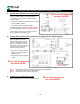

Direction of Flow
TS Series flow meters can operate in either direction.
Standard assembly, when facing the flow meter, has the
flow going Left-to-Right, unless specified differently at time
of the order. A label with the word INLET is placed on the
inlet flange, as assembled at the factory. To change the
direction of flow:
1. Reverse the position of any accessories attached to the
flow meter.
2. If Quadrature pulse signal is used, reverse output leads
for channels A & B on the TBB (or SCL):
TBB SCL
L-to-R R-to-L
WHITE: On A On B
GREEN: On B On A
NOTE: The ELNC register is not W&M certified in
the EU.
The SCL is not yet approved for use in
the EU.
1 . 8
Flow Meter Communications & Direction of Flow
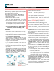
TS Series meters in F●● & W●● assembly have an internal
pulser. The pulse signal generated by the flow meter, can
be fed directly to most electronic registers. In such assem-
blies, flow meter calibration (or re-calibration) is through
correction of the K Factor (number of pulses/unit volume) in
the electronic register.
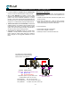
In some cases an SCL board (#13) is added to the flow me-
ter assembly. This signal conditioner is added when:
1. Flow meter pulse frequency exceeds the electronic
register capacity at maximum flow rate. This can occur
at surprisingly low flow rates (see below).
2.
The electronic register requires a scaled pulse value
(1, 10, 100 or 1000 pulses/volume unit).
3.
Local authorities demand a mechanical calibration de-
vice. The SCL includes two dials with setting from 00
to 99. Changing the setting by 1, represents approx.
0.03% correction to the pulse signal.
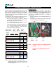
NOTE: K Factors shown here are nominal (average).
Individual flow meters can vary slightly; and all flow
meters will shift to some degree with viscosity fluctu-
ations (see page 1.14)
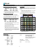
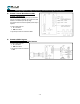
Register model:
LCR-II™
Frequency limit: 625 Hz
FLOW
METER
MODEL
GP M LPM
P P G ppl
TS10C
40 150
2176 575
1451
Hz
0.35
ms
TS15C
60 230
1152 304 1152
Hz
0.43
ms
TS20C, NS
150 570
395 104 988
Hz
0.51
ms
TS30C,
200 760
276 73 920
Hz
0.54
ms
Interm. dut
y
250 945
1150
Hz
0.44
ms
Interm. dut
y
300 1135
1380
Hz
0.36
ms
With EL0300-3-13 = 100 PPG scaler
TS10C
40 150
100 26
67
Hz
1.30
ms
TS15C
60 230
100 26 100
Hz
1.30
ms
TS20C, NS
150 570
100 26 250
Hz
1.30
ms
TS30C,
200 760
100 26 333
Hz
1.30
ms
Interm. dut
y
231 875
385
Hz
1.30
ms
If higher flow rates occur, use EL0300-3-18 (see below)
With EL0300-3-18 = 10 PPL scaler
TS10C
40 150
37.9 10
25
Hz
2.50
ms
TS15C
60 230
37.9 10 38
Hz
2.50
ms
TS20C, NS
150 570
37.9 10 95
Hz
2.50
ms
TS30C,
200 760
37.9 10 126
Hz
2.50
ms
Interm. dut
y
250 945
158
Hz
2.50
ms
Interm. dut
y
300 1135
189
Hz
2.50
ms
EMR
3
Please refer to FPP261 for other registers.
ELNC
400 Hz
CAPACITY
K Factor
F
requency
(H
z
)
&
Pulse ON time at
100% of model cap.
1667 Hz