
Instruction Manual
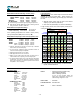
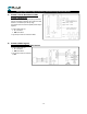

Flow Meter Assembly No. & Part No.
Model No. + Assy. No. + Variable Identifiers = Part No.
Model No. : 5 digits; referenced in certifications, etc.
Assy. No. : 3 digits, define basic type & configuration
Variables : Identified in remainder of the Part No.
The Part No., is found on flow meter Spec Plate, together
with the Serial No. The P/No. can be as short as 8, or as
long as 18 positions; where each position has some signifi-
cance. The key identifier for the purpose of identifying spare
parts is in all cases Pos. 10 which identifies flow meter inter-
nals:
B = LV, PPS/carbon rotors, Teflon seals (standard)
C = HT, PPS/carbon rotors, Teflon seals
D = HV, PPS/carbon rotors, Teflon seals
E = LV, PPS/Teflon rotors, Teflon seals
P = HT, PPS/Teflon rotors, Teflon seals
H = HV, PPS/Teflon rotors, Teflon seals
If it is necessary to replace the board found in the pulser
compartment in the front cover, the key identifiers are:
Fxx assemblies, Pos. 11:
5-12VDC 24VDC
1-9 or T same : EL0304 Terminal Block Board
G H : EL0300-3-13_ 100 PPG scaler
L K : EL0300-3-18_ 10 PPL scaler
A A : EL0305 TBB/Amplifier
F J : EL0306 TBB/Quadrature Filter
Wxx assemblies, Pos. 12:
5-12VDC 24VDC
T T : EL0304 Terminal Block Board
G H : EL0300-3-13_ 100 PPG scaler
L K : EL0300-3-18_ 10 PPL scaler
A A : EL0305 TBB/Amplifier
F J : EL0306 TBB/Quadrature Filter
Fxx = Flow Meter with Register Mounting flange:
Position 1-5 : Model No. (capacity & materials)
Position 6 : F = Electronic, with mounting flange
Position 7 : Register included, if any
Position 8 : Accessories included, if any
Position 9 : Flange type
Position 10 : Rotor type, Bearing Material & Seals
Position 11 : Register & Printer included
Position 12 : UL or ATEX listed components
Position 13 : Register language
Position 14 : Strainer identifier
Position 15 : Strainer basket mesh identifier
Pos. 16-17 : Solenoid valve type & voltage
Position 18 : no significance at this time
Wxx = Flow Meter without Register Mounting flange:
Position 1-5 : Model No. (capacity & materials)
Position 6 : W = Electronic, without mounting flange
Position 7 : Register included, if any
Position 8 : Accessories included, if any
Position 9 : Flange type
Position 10 : Rotor type, Bearing Material & Seals
Position 11 : Internal signal conditioner, if any
Position 12 : UL or ATEX cable gland, if any
Position 13 : Register enclosure, if any
Position 14 : Strainer identifier
Position 15 : Strainer basket mesh identifier
Pos. 16-17 : Solenoid valve type & voltage
Position 18 : no significance at this time
1 . 5
1 =
Register Ready (no register from Tuthill)
5 =
with EMR3 register, without Temp probe.
6 =
with EMR3 register, with Temp probe
(select strainer with thermo well if ATC)
7 =
with SCL & ELNC register
W_X = without register flange
0 =
Flow Sensor (nothing attached)
1 =
1x PIA-300 amplifier (2 x single channel)
2 =
2x PIA-300 amplifier (1 x Quadrature)
3 =
PC58
4 =
PC58 + PIA-300
5 =
PC58 + 4-20 mA signal
6 =
PC58 + 4-20 mA signal + multipoint calibration
7 =
PC58 + 4-20 mA + PIA-300
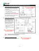
Assy No.
(pos. 6-8 in P/No.)
W_4 W_5
Pos. 7 identifier inserted from list below
METER + STRAINER + AIR ELIM.
F_X = with Register mounting flange
W_6
F_4 F_6F_5