TS Series W & F Assy. Stainless Steel, Electronic FPPMSW12, Rev. 2010-10 Installation, Operation & Parts Manual Flow meter P/No.: __________________ Flow meter S/No.
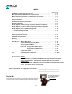
INDEX Section . Page FPP Meters and Principle of Operation . . . . . . . . . . . . . . . . . . . . . . . . . . . . . . . . 1 . 3 Meter Specifications & Materials of Construction . . . . . . . . . . . . . . . . . . . . . . . 1 . 4 Model, Assembly & Part No. (= identification of internals) . . . . . . . . . . . . . . . . 1 . 5 Safety Instructions . . . . . . . . . . . . . . . . . . . . . . . . . . . . . . . . . . . . . . . . . . . . . . . . . 1 . 6-7 Installation & Operation Procedures . . . . . . . . . . .
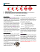
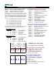
TS Series, Principle of Operation Only 2 moving parts. Patented ‘Waveform’ oval gears = sustained accuracy with a minimum of maintenance. No metal-to-metal contact in measuring chamber or in bearings. The lowest differential pressure values amongst rotary PD meters. => Lower Cost of Ownership! About FPP Meters We thank you for purchasing an FPP Meter for liquid measurement service. FPP Meters, formerly Fluid Power Products, is now a trade name of Tuthill Transfer Systems.
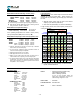
Flow Meter Specifications Liquid Viscosity³: With standard LV rotors, meters may be used to full nominal capacity up to 300 cPs (1500 SSU). When viscosity can exceed 300 cPs (1500 SSU), high viscosity (HV) rotors must be used.
Flow Meter Assembly No. & Part No. Model No. + Assy. No. + Variable Identifiers = Part No. Model No. : 5 digits; referenced in certifications, etc. Assy. No. : 3 digits, define basic type & configuration Variables : Identified in remainder of the Part No. Fxx = Flow Meter with Register Mounting flange: Position 1-5 : Model No. (capacity & materials) The Part No., is found on flow meter Spec Plate, together with the Serial No. The P/No.
Installation, Start-Up & Operation SAFETY INSTRUCTIONS OPERATING TEMPERATURE TS Series assemblies are rated for: F●● assy See register temperature rating W●● assy -40°F/+225°F (-40°C/+107°C). Make sure that all necessary safety precautions have been taken, including proper clothing, personal safety equipment and fire safety equipment if required. However: Before Start-Up of the Flow Meter, make certain that: 1. The meter is properly mounted, secured and piped. 2. All connections are tight. 3.
Installation continued & Start-Up/Operation In critical installations a by-pass line is recommended, so flow can continue while flow meter is being serviced. When an Air Eliminator is included in the flow meter assembly, the strainer/air eliminator must be in horizontal position, since the air eliminator operates on a gravity principle. A few drops of liquid may be expelled when the air eliminator vents, so vent ports should be piped back to storage or to a collection tank (sloping towards the tank).
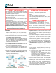
Flow Meter Communications & Direction of Flow TS Series meters in F●● & W●● assembly have an internal pulser. The pulse signal generated by the flow meter, can be fed directly to most electronic registers. In such assemblies, flow meter calibration (or re-calibration) is through correction of the K Factor (number of pulses/unit volume) in the electronic register. Direction of Flow TS Series flow meters can operate in either direction.
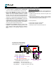
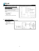
Wiring Diagram to High Frequency Quadrature Register/Controller A. EL0304 Terminal Block Board (TBB) EL0305 TBB/Amplifier EL0305 is used for remote high frequency electronic registers accepting quadrature signal, when the cable distance is in 200-600’ (60-180 m) range. For greater distances external amplifier (2xPIA-300) is required. Pulser cable plugs into: J1 on EL0304 AMP on EL0305 Signal output cable is connected to TB1 B.
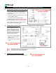
Wiring to Low Frequency Quadrature Register/Controller C. EL0300 Scaler/Calibrator/Linearizer (SCL) EL5591 or EL0303 While the SCL can have multiple functions, in many cases it is included strictly as a signal conditioner (= ‘Jitter filter’). In those cases, only the calibrator function is active. SCL is not yet approved for use in the EU. Pulser plug is removed. Pulser leads are connected directly to TB2 on the SCL. Signal output cable is connected to TB1.
Control Drawing CD1001 The ELNC is not W&M certified in the EU. 1 .
Control Drawing CD1000, left side The ELNC is not W&M certified in the EU. 1 .
Control Drawing CD1000, right side The ELNC is not W&M certified in the EU. 1 .
Flow Meter Calibration Procedures & Methods Flow meters subject to Weights&Measures regulations, or used in systems where the flow rate can fluctuate, should be tested at minimum, intermediate & maximum flow rates. In non-W&M service, a flow meter always operating at a steady flow rate, can be tested at that flow rate only. All calibration tests should be: Of at least 60 second duration, to minimize the effect of flow meter error during start-up and shut-down.
WET vs DRY Pulser This flow meter exists in 2 generations: 1st generation, manufactured from 2007 through 2009 Has pulser (#10) in SS housing, exposed to the operating fluid. Pulser is sealed with an O-ring (#16), held in place by a heavy retainer (#11) with a LARGE center hole. Meter must be isolated & drained if pulser must be inspected. 2nd generation, introduced gradually; only type as of Jan 1st, 2010 Pulser (#10) without housing, sensing magnet position through the wall.
Trouble Shooting the Flow Meter Installation, Maintenance & Service must be performed by personnel: A. Qualified to work on this type of equipment. B. Familiar with all applicable local codes and ordinances covering the type of service, where the flow meter is used (gasoline, LPG, etc.). Reduced Flow Rate Strainer basket partially blocked. Clean the basket. Pump not functioning correctly. Repair pump. Valve stuck in partially closed position. Check valves and repair.
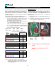
Flow Meter - Disassembly This electronic flow meter, with only 2 moving parts, is available in two versions: F●● Assembly with register installed In this version the electronic register is attached to the register mounting pad (#7), which is installed directly on top of flow meter case (#1). This permits service of the flow meter without removing the electronic register, eliminating the risk of unintentional swapping of registers between flow meters.
Flow Meter - Disassembly When servicing meters with Teflon seals, replace all seals every time the flow meter is serviced. A. Pulser O-ring (16), or Pulser (10) First relieve system pressure and drain the flow meter. 1. Remove 4 screws (12a) from the dust cover (12), and detach the dust cover. 2. Release signal cable from TB1 on the board (13). 3. Release pulser (10) leads from J1 on terminal block board/SCL (13). 4. Remove 2 terminal block board/SCL screws (13a), and take the board (13) out.
TS Series - Exploded View, Electronic When servicing meters with Teflon seals, replace all seals every time the flow meter is serviced. make sure that coupling is horizontal to match up to the gear. Gently push into place. Turn the magnet (29C) with two fingers, to ensure that gears are turning freely in the measuring chamber. Re-install the front cover (5) and O-ring (17). Make sure that the drain plug (24) is located at the bottom of the flow meter. Check all O-ring seals for damage.
Parts List, TS10C, TS15C, TS20C & TS30C - WET pulser Assy No. ITEM Fxx Wxx DESCRIPTION Mdl TS10C Mdl TS15C Mdl TS20C Mdl TS30C QTY & P/No. QTY & P/No. QTY & P/No. QTY & P/No. 1 2 + Std. + opt.
Exploded View - WET Pulser 1 .
Parts List, TS10C, TS15C, TS20C & TS30C - DRY pulser Assy No. ITEM Fxx Wxx DESCRIPTION Mdl TS10C Mdl TS15C Mdl TS20C Mdl TS30C QTY & P/No. QTY & P/No. QTY & P/No. QTY & P/No. 1 2 + Std. + opt.
Exploded View - DRY pulser 1 .
Torque/Tools Table q IT E M 9 11a 12a 13a 18 19 20 21 24 25 26 30 D E S C R IP T IO N Stand-off Tool Torque specification Retainer plate screw Tool Torque specification Dust cover screw Tool Torque specification TBB/SCL screw Tool Torque specification Retainer clamp screw Tool Torque specification Cover screw Tool Torque specification Post/Bearing plate screw Tool Torque specification Pedestal screw Tool Torque specification Cover drain plug Tool Torque specification Cable port plug Tool Torque specifi
SCL is not yet approved for use in the EU. Optional SCL in place of TBB SCL (Scaler/Calibrator/Linearizer) Description: Tuthill SCL is a small electronic device designed to provide the function of a pulse Scaler, an electronic Calibrator and Linearizer.
SCL is not yet approved for use in the EU. SCL, continued METER CALIBRATION: Flow meter re-calibration should be on a volume equal to 1 minute of flow at maximum flow rate. All tests should be performed 3 times under identical conditions to confirm repeatability. Maintain a permanent file for each flow meter, and record % change each time the meter is recalibrated.
This page is intentionally left blank 1 .
This page is intentionally left blank 1 .