
Instruction Manual


1 . 6
Flow Meter Part No.
Flow Meter Part No.
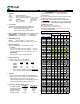
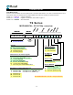
Most flow meter assemblies can be fully defined with a 10 position Part Number. Only when non-standard options are se-
lected (pulser, seals, non-standard rotors or strainer basket), does it become necessary to extend the Part No.:
Position 1-5 = Model No. Capacity & Materials
Position 6-8 = Assy. No. Register & Accessories, refer to table on page 1.7.
Position 9-17 = VariablesVariablesVariables See codes below.
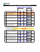
MECHANICAL, 2010 P/No. overview
TS Series
R
O
T
O
R
S
S
T
R
A
I
N
E
R
M
e
s
h
s
i
z
e
P
U
L
S
E
R
S
E
A
L
S
C
A
L
I
B
R
.
F
L
A
N
G
E
S
MODEL No. ASSY No.
Area Shaded YELLOW = non-std => Longer Lead Time!
Whole Imp gallon,
not on TS10 or TS15
Rotor/Bearin
g
materials & Rotor t
y
pe
U
1/10 Imp gallon,
not on TS30
100 mesh, optional (2" only)
Std for
HT
service (
'YELLOW'
in p/l)
0
PPS/carbon,
HV
PPS/carbon,
HT
8
80 mesh, optional (3" only)
2
20 m esh, s td/HV rotors
1211
Std. Strainer
(blank if 40 mesh)
40 mesh, std/LV & HT rotors
Strainer BASKET
See Assy
Chart
4
S
Dekaliter,
not on TS10 or TS15
AA welding flanges
H
Hi Cap strainer
1/10 liter,
TS10 onl
y
L
8
C
18
Whole liter,
not on TS10
Flan
g
es
150# RF ANSI adaptors,
CS
CS welding flanges
H
Calibration for mechanical re
g
iste
r
S20AV_
A
B
NPT companion flanges
BSP companion flanges
A
Anodized Aluminum
T
R
O
T
O
R
S
If all STANDARD selections, these identifiers are not filled in.
PPS/Teflon,
HT
M
14 15
PPS/Teflon,
LV
1/10 gallon,
not on TS30
S
T
R
A
I
N
E
R
M
e
s
h
s
i
z
e
567 17
P
U
L
S
E
R
S
E
A
L
S
C
A
L
I
B
R
.
F
L
A
N
G
E
S
MODEL No. ASSY No.
1312 3 4 10
_
169
100:1 solid state
C
F
X
D
S
none (standard)
10:1 dry reed
M
L
I
C
Standard =
'GREEN'
price in price lists.
Teflon,
I
B
PPS/carbon,
LV
D
G
T
Whole gallon,
not on TS10 or TS15
Y
Std for
HV
service (
'BLUE'
in p/l)
Strainer TYPE
J
PPS/Teflon,
HV
Seal Material
Pulser on Re
g
ister
A
B
Viton,