TS Series V Assy. Anodized Aluminum, Mechanical Drive Manual FPPMSV02, Rev. 2010-12 Installation, Operation & Parts Manual Flow meter P/No.: TS_________________ Flow meter S/No.
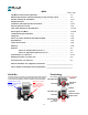
INDEX Section . Page FPP Meters and Principle of Operation . . . . . . . . . . . . . . . . . . . . . . . . . . . . . . . . . . . . . . 1.3 Material Specifications, Capacity & derating on high viscosity liquids . . . . . . . . . . . . 1.4 Part No. and Assy No. break-down . . . . . . . . . . . . . . . . . . . . . . . . . . . . . . . . . . . . . . . . . . 1 . 6-7 Safety Instructions . . . . . . . . . . . . . . . . . . . . . . . . . . . . . . . . . . . . . . . . . . . . . . . . . . . . . . . 1.
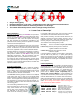
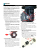
TS Series, Principle of Operation Only 2 moving parts. Patented ‘Waveform’ oval gears = sustained accuracy with a minimum of maintenance. No metal-to-metal contact in measuring chamber or in bearings. The lowest differential pressure values amongst rotary PD meters. => Lower Cost of Ownership! About FPP Meters We thank you for purchasing an FPP Meter for liquid measurement service. FPP Meters, formerly Fluid Power Products, is now a trade name of Tuthill Transfer Systems.
Materials Case Rotors (oval gears) Posts Seals TS Series, Anodized Aluminum - Specifications for V●● assemblies Flow Meter nominal capacity: ● Normal operating range is w ith 10:1 turn-dow n from model : Anodized aluminum : PPS with carbon bearings, TeflonTM bearings optional. : HC303SS : VitonTM standard, TeflonTM optional. nominal capacity. See cover for rotor & seal materials in this meter.
This page is intentionally left blank 1.
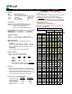
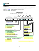
Flow Meter Part No. Flow Meter Part No. Most flow meter assemblies can be fully defined with a 10 position Part Number. Only when non-standard options are selected (pulser, seals, non-standard rotors or strainer basket), does it become necessary to extend the Part No.: Position 1-5 = Model No. Position 6-8 = Assy. No. Position 9-17 = Variables Capacity & Materials Register & Accessories, refer to table on page 1.7. See codes below. TS Series LS AI NE R Me sh siz e ST R PU L SE A SE R S TO R R.
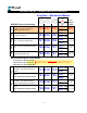
Flow Meter Assy No. = Register & Accessory combination Assy Nos.
Installation, Start-Up & Operation SAFETY INSTRUCTIONS OPERATING TEMPERATURE TS Series V●● assemblies are rated for operation from -40°F/+180°F (-40°C/+80°C). However: Make sure that all necessary safety precautions have been taken, including proper clothing, personal safety equipment and fire safety equipment if required. They are not suitable for cryogenic service. When operating temperature exceeds +120°F (+50°C), pressure rating is reduced. Please refer to FPP Technical Manual for details.
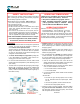
Installation & Start-Up/Operation Apply pipe compound to male threads, to install the two Thermal relief valves are recommended, and should be companion flanges. Tighten to a position, that allows the meter to bolt to the companion flanges, free of pipe stress. installed whenever it is possible to block (isolate) the flow meter between two valves. The pressure rise in a closed system, from just a few degrees increase in temperature, can be many times normal working pressure.
Changing Direction of Flow TS Series flow meters can operate in either direction. Standard assembly, when facing the flow meter, has the flow going Left-to-Right, unless specified differently at time of the order. A label with the word INLET is placed on the inlet flange, as assembled at the factory. 14 When the meter is first installed, check that the register is turning correctly when you start the flow.
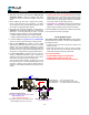
Calibration, Mechanical Flow Meters Mechanical TS Series meters have a mechanical drive train directly from the rotors (oval gears) to the register. To convert rotor movement to volume reading on the register, this drive train includes 3 calibration components: W&M Certifications: TS10A TS15A TS20A TS30A US US & Canada US, Canada, EU & Australia US, Canada, EU & Australia Packing gland pinion (11D) can have 12 or 24 teeth, while the face gear (11E) always has 24 teeth, resulting in a 1:1 or 2:1 ratio.
Flow Meter Calibration When prover/master meter reading is less than flow Procedures & Methods meter register reading, add percentage calculated by turning the calibrator in the + volume direction. Flow meters used in systems where the flow rate can fluctuate, should be tested at minimum, intermediate & maximum flow rates. In non-W&M service, a flow meter always operating at a steady flow rate, can be tested at that flow only. All tests should be repeated 3 times to confirm repeatability.
Servicing the Flow Meter ! SAFETY INSTRUCTIONS Always coat bolt threads with an anti-seize, or an appropriate lubricant to prevent thread damage, and to assure proper torque values are applied when reassembling. ! REMOVE ALL INTERNAL PRESSURE If flow meter threads are damaged, repair using inserts. BEFORE OPENING THE FLOW METER.
Servicing the Flow Meter B. Packing Gland O-ring (11B) E. Packing Gland Assembly (11) First relieve system pressure and drain the flow meter. Then follow instructions for above for removal of calibrator drive shaft assembly. Remove E-ring (11C) from the packing gland assembly, and pull off the pinion (11D). Remove three screws (13) from the packing gland retainer (12). Remove the retainer Packing Gland O-ring and/or Packing Gland assembly can now be replaced.
Servicing the Flow Meter Remove 4 screws (6) from the post plate (3). The post For optional flow meter accessories: plate assembly can now be pulled off dowel pins (5), using a 5/16-8 x 1” jack bolt if necessary. Strainer Air Eliminator The posts are expected to last through several sets of rotors. When the posts show signs of wear, or if they have been bent due to hydraulic shock, the complete postplate assembly must be replaced.
Flange Kits & Parts for Flanges Tuthill TS Series flow meters come standard with bolted companion flanges, with either NPT or BSP threaded ports. Other options are welding flanges (aluminum or steel), and 150# RF ANSI adaptors (steel).
Troubleshooting the Flow Meter Prior to opening or disassembly of any flow meter, all internal pressure must be relieved and all liquid must be drained. This must be done in accordance with applicable company and local codes & ordinances. Make sure that all necessary safety precautions have been taken, including proper clothing, personal safety equipment and fire safety equipment if required. No Flow Blocked strainer basket. Clean the basket. Faulty or non-functioning pump. Repair pump.
Parts List TS10A, OS ITEM 1 DESCRIPTION Meter Body Depth across body: 1 MB2560 TS10A, NS QTY P/No. 1 MB2565 1.47” (37 mm) TS15A P/No. 1 MB2575 QTY 1.97” (50 mm) TS20A P/No. 1 MB2395 QTY 3.46” (88 mm) TS30A P/No. 1 MB5201-1 QTY 3.46” (88 mm) 4.96” (126 mm) 2 Gear Set, Opt. 3 4 4a 4b-I Post Plate assy. Gear Plate assy.
TS Series - Exploded View, Mechanical (V●● Assy.
Tools & Torque Chart IT E M 6 10 13 16 17 18 20 24 25 26 27 30 D E S C R IP T IO N Post/Bearing plate screw Tool Torque specification Cover screw Tool Torque specification Packing gland retainer screw Tool Torque specification Dust cover screws Tool Torque specification Calibrator bushing set screw Tool Torque specification Calibrator mounting screw Tool Torque specification Pedestal screw Tool Torque specification Cover drain plug Tool Torque specification RAD housing/flange screw Tool Torque specificat