
Instructions / Assembly

fillrite.com
6
| FR700V SERIES FUEL TRANSFER PUMPS
INSTALLATION AND OPERATION MANUAL
Wiring Procedure
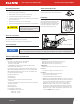
1. Remove the junction box cover and straighten the wires to make sure the stripped wire ends are accessible outside the junction box.
2. Connect the pump wires to the power supply lines according to the diagram. Be certain to properly insulate the connections with the appropriate wire nuts or other connectors.
Note that the ground wire MUST be connected.
3. Tuck the wires back into the junction box, verify proper placement of gasket, align cover with junction box holes and reinstall screws. Torque each screw to 90 ± 9 in-lbs.
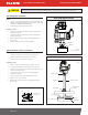
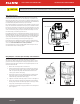
Use the Voltage Selector Switch on the end of the pump to select the input voltage for the pump. NOTE: The pump comes from the factory pre-set to 115V AC position.
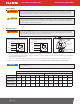
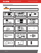
Electric Wiring
115 VOLT WIRE DIAGRAM AUX LEAD RATED 1.0 AMP 230 VOLT WIRE DIAGRAM AUX LEAD RATED 1.0 AMP
MOTOR
ORANGE
BLACK
BLACK WITH
WHITE STRIPE
GREEN
GRN
AC
AC
AUX
MOTOR
ORANGE
BLACK
WHITE
GREEN
GRN
NEU
AC
AUX
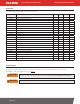
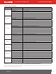
MAX CABLE LENGTH IN FEET (METERS)
SOLID WIRE STRANDED WIRE
AWG
14 12 10 8 6 4 14 12 10 8 6 4
115V AC
(60Hz motor)
62
(18.9)
99
(30.2)
158
(48.2)
250
(76.2)
-- --
61
(18.6)
96
(29.3)
154
(46.9)
245
(74.7)
389
(118.6)
620
(189.0)
230V AC
(50Hz motor)
214
(65.2)
340
(103.6)
542
(165.2)
859
(261.8)
-- --
209
(63.7)
331
(100.9)
529
(161.2)
844
(257. 3)
-- --
230V AC
(60Hz motor)
221
(67.4)
351
(107.0)
560
(170.7)
887
(270.4)
-- --
216
(65.8)
342
(104.2)
546
(166.4)
871
(265.5)
-- --
All pumps should be operated at the Rated Nameplate Voltage. Power should be supplied to the pump from a dedicated 20 amp circuit breaker.
No other equipment should be powered by this circuit. Wiring must be of sufficient size to carry the correct current for the pump. Voltage drop
will vary with distance to pump and size of wire; refer to the National Electrical Code (NEC), or local codes, for Voltage Drop Compensation to be
sure you are using the correct size wire for your application.
Electrical wiring should be performed ONLY by a licensed electrician in compliance with local, state, and national electrical code NEC/ANSI/
NFPA 70, NFPA30, and NFPA 30A, as appropriate to the intended use of the pump. Threaded rigid conduit, sealed fittings, and conductor seal
should be used. The pump must be properly grounded. Improper installation or use of this pump can result in serious bodily injury, or death!
CAUTION
WARNING
The “AUX.” wire IS A LIVE WIRE when the switch is on! The “AUX” lead wire is insulated and enclosed when shipped. DO NOT connect this wire
without first verifying the “ON” line voltage of the wire for compatibility with the equipment to be installed. Maximum amperage on this wire is
1 amp. The “AUX” wire must be insulated and enclosed in the junction box if not used.
WARNING
Be certain the gasket for the cover is in place, and the screws draw the cover down tight over the junction box. There must be no gap between
the junction box and it’s cover.
NOTICE
Pump Switch Lever
ON
Conduit opening
1/2" NPT
OFF