
Instructions / Assembly

fillrite.com
11
| FR700V SERIES FUEL TRANSFER PUMPS
INSTALLATION AND OPERATION MANUAL
C
M
Y
CM
MY
CY
CMY
K
700H1471 Visuals sht2_G.pdf 1 9/8/20 12:52 PM
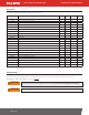
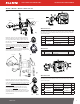
No. Part / Kit # Description Qty.
1 807C 807C Meter (Gallon) 1
2
701H0934
Meter Flange 1
3 Gasket, Lathe Cut, Nitrile 1
1 807CL 807CL Meter (Liter) 1
No. Gallon Kit Number Description Liter Kit Number Qty.
1 901C 901C Meter (Gallons) -- 1
2
900 Meter
(Gallon) Kit #
901CMK300V
Meter Flange
900 Meter
(Liter) Kit #
901CLMK300V
1
3 Meter Gasket 2
4 1" Meter Fitting 1
1 -- 901CL Meter (Liters)
901CL
1
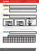
FR700V / FR701V / FR710V / FR711V Parts List
No. Part / Kit # Description Qty.
1 700H0128 1" Outlet Flange 1
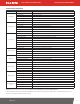
FR710V Parts
FR701V Parts List
The FR701V configuration adds a 807C Series mechanical meter, inlet meter flange, outlet
meter flange, the associated attaching hardware, and gaskets. This package is available
in gallon or liter register.
FR711V Parts List
The FR711V configuration adds a 901C Series mechanical meter, inlet meter flange, outlet
meter flange, the associated attaching hardware, and gaskets. This package is available
in gallon or liter register.
KIT700RG
KIT700CV
KIT700SL
KIT700SG
KIT700SW
KIT700BG
KIT120NB
KIT700JC
700KTF2659
KIT700RG
KIT700SL
KIT700SG
KIT700BG
KIT700CV
KIT700SW
KIT120NB
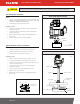
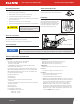
Please review the following visual indicators to determine which FR700V Series model you
have:
Examine the casting on the side of the pump containing the
switch and nozzle boot. There will be an emblem etched into
the casting. Underneath the casting, you will see a date code.
If the date code is only 4 characters or numbers long, you have
the older design.
Additionally, on the other side of the pump, the cast iron pump
housing is not angled and contain the words “Strainer” and
“Bypass Valve” etched directly into the casting. If your pump
matches these descriptions, the check valve is located on the
outlet side of your pump. It will also utilize the longer of the two
strainer assemblies available in KIT700SG.
C
M
Y
CM
MY
CY
CMY
K
700H1471 Visuals sht2_B.pdf 1 9/8/20 12:54 PM
C
M
Y
CM
MY
CY
CMY
K
700H1471 Visuals sht2_G.pdf 1 9/8/20 12:52 PM
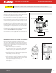
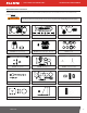
Examine the casting on the side of the pump containing the
switch and nozzle boot. There will be an emblem etched into the
casting. Underneath the casting, you will see a date code. If the
date code is 5 characters long and ends in the letter “B”, you
have the new design.
Additionally, on the other side of the pump, the cast iron
pump housing has angled edges and does not contain any
words etched into the casting. If your pump matches these
descriptions, the check valve is located on the inlet side of your
pump. It will utilize the shorter of the two strainer assemblies
available in KIT700SG.
C
M
Y
CM
MY
CY
CMY
K
700H1471 Visuals sht2_G.pdf 1 9/8/20 12:52 PM
B
2
3
3
4