FR700V SERIES FUEL TRANSFER PUMPS Installation and Operation Manual
| INSTALLATION AND OPERATION MANUAL FR700V SERIES FUEL TRANSFER PUMPS Table of Contents Thank You! .............................................................................................................. 2 Thank You! Warranty Policy........................................................................................................ 2 Anti-Siphon Device..................................................................................................
| FR700V SERIES FUEL TRANSFER PUMPS INSTALLATION AND OPERATION MANUAL About This Manual From initial concept and design through its final production, your Fill-Rite pump is built to give you years of trouble-free use. To insure it provides that service, it is critical that you read this entire manual prior to attempting to install or operate your new pump.
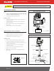
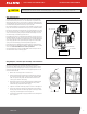
| CAUTION INSTALLATION AND OPERATION MANUAL FR700V SERIES FUEL TRANSFER PUMPS Threaded pipe joints and connections should be sealed with the appropriate sealant or sealant tape to minimize the possibility of leaks. Typical Skid Tank Installation SKID TANK INSTALLATION Materials • 1-1/4" pipe cut to a length that will terminate at least 3" from the bottom of the tank when installed into the tank adapter with the tank adapter installed into the tank flange (see SKID TANK INSTALLATION diagram).
| CAUTION INSTALLATION AND OPERATION MANUAL FR700V SERIES FUEL TRANSFER PUMPS Threaded pipe joints and connections should be sealed with the appropriate sealant or sealant tape to minimize the possibility of leaks. Anti-Siphon Device Your FR700V Series pump comes from the factory ready to install an anti-siphon tube back to the tank. An anti-siphon device (a.k.a.
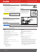
| INSTALLATION AND OPERATION MANUAL FR700V SERIES FUEL TRANSFER PUMPS Electric Wiring WARNING Electrical wiring should be performed ONLY by a licensed electrician in compliance with local, state, and national electrical code NEC/ANSI/ NFPA 70, NFPA30, and NFPA 30A, as appropriate to the intended use of the pump. Threaded rigid conduit, sealed fittings, and conductor seal should be used. The pump must be properly grounded.
| Operating Instructions Safety Testing Approvals 1. Reset Meter to “0” (if applicable). 2. Remove dispensing nozzle from nozzle boot. 3. Move the switch lever to the “ON” position to power the pump. 4. Insert the dispensing nozzle into the container to be filled. 5. Operate the nozzle to dispense fluid; release nozzle when the desired amount of fluid has been dispensed. 6. Move switch lever to the “OFF” position to stop the pump. 7.
| INSTALLATION AND OPERATION MANUAL FR700V SERIES FUEL TRANSFER PUMPS Accessories A wide variety of accessories are available to help you maximize the performance of your FR700V Series pump. Listed below are the applicable available accessories for your specific product. Please contact your authorized Fill-Rite distributor to purchase the accessories you need.
| FR700V SERIES FUEL TRANSFER PUMPS INSTALLATION AND OPERATION MANUAL Troubleshooting (Continued) Symptom Fluid leakage Pump won't prime Low capacity Pump runs slowly Motor stalls Motor overheats Motor inoperative Pump hums but will not operate Cause Solution 1. Bad o-ring gasket Check all o-ring gaskets 2. Dirty shaft seal Clean seal & seal cavity 3. Bad shaft seal Replace seal 4. Incompatible fluid Refer wetted parts list to fluid manufacturer 5.
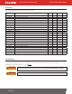
| FR700V SERIES FUEL TRANSFER PUMPS INSTALLATION AND OPERATION MANUAL Replacement Parts Information For repairs or routine maintenance, Fill-Rite offers the parts you need. The following parts diagram and list covers all applicable parts for your Fill-Rite product. These parts can be obtained through any authorized Fill-Rite dealer. Be sure to use only genuine Fill-Rite replacement parts for your service and maintenance needs. For a list of authorized dealers, please visit fillrite.com.
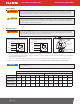
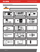
| INSTALLATION AND OPERATION MANUAL FR700V SERIES FUEL TRANSFER PUMPS FR700V / FR701V / FR710V / FR711V Parts List Please review the following visual indicators to determine which FR700V Series model you have: KIT120NB KIT700CV KIT700RG KIT700JC KIT700SL KIT700SW FR701V Parts List KIT700SG 700H1471 Visuals sht2_G.pdf 1 9/8/20 The FR701V configuration adds a 807C Series mechanical meter, inlet meter flange, outlet meter flange, the associated attaching hardware, and gaskets.
NOTICE The following information is for suffix “E” pumps and meters (designed for use outside the United States and Canada)! Refer to the information label applied to your pump to see if it is applicable. Materials of Construction Materials of construction of the external surface of the unit are: painted steel; painted cast iron; painted aluminum; zinc plated steel.