
Instructions / Assembly

fillrite.com
6
| H-SERIES FUEL TRANSFER PUMPS
INSTALLATION AND OPERATION MANUAL
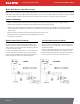
Installation Procedure
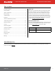
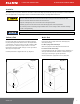
Step 1: (Optional) Inlet Flange Removal
Loosen (4) 1/4" bolts using 7/16" wrench or socket. Detach inlet bung
frompump, retain bolts, screen, and gasket.
Step 2: Using either included suction pipe or custom pipe, thread
pipe into inlet bung 1.5 to 2.5 turns past hand tight with pipe wrench.
Useappropriate sealant for fueltransfer.
Step 3: Thread inlet bung with attached suction pipe onto tank 1.5 to
2.5turns past hand tight. Useappropriate sealant for fueltransfer.
Step 4: (Only if Step 1 utilized) Place screen in screen pocket on the inlet
bung, mount gasket, then place pump on tank bung. Align holes and insert
(4) 1/4" bolts and tighten with 7/16" wrench to 40in.-lbs.minimum.
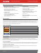
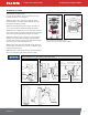
Step 5: Remove junction box cover via (2) T-25 screws and locate wires.
DCVoltage: 2 wires, Black and Red; AC Voltage: 3 wires, Black, White,
and Green which is attached to internal ground screw. Ensure that gasket
remains in place upon re-attachment of junction box.
Step 6: Feed wires from power source through NPT
†
opening into junction
box. For DC models, use the black cable connector
*
. For AC models, attach
conduit directly to NPT
†
opening.
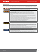
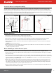
Step 7: Nozzle boot is attached to switch plate via (1) 5/16" bolt torqued to
40 in-lbs. The nozzle boot has two available position placements.
* Black cable gland only included with DC models
†
1/2" NPT to cable gland, bronze fitting per ATEX onHE Models
Maintain a minimum 1-2" separation from pipe end to bottomof tank.
(2) T-25
SCREWS
JUNCTION BOX CAP
GASKET
Step 5
Step 2
Step 3
PUMP
SCREEN
POCKET
INLET
FLANGE
GASKET
TANK
BUNG
SCREEN
Step 4
½" NPT
CONDUIT HOLE,
THREADED
(2) T-25
TORX SCREWS
EXTERNAL GREEN
GROUND SCREW
JUNCTION
BOX GASKET
JUNCTION BOX CAP
(CAN BE ROTATED 180°)
EARTH GROUND
SYMBOL
Step 6
BOLT
HOLE
POSITION
POST
5/16" BOLT,
40 IN-LBS
Step 7