A Sierra Monitor Company Driver Manual (Supplement to the FieldServer Instruction Manual) FS-8700-17 Optomux APPLICABILITY & EFFECTIVITY Effective for all systems manufactured after January 1, 1999 Instruction Manual Part Number FS-8700-01 2/18/2004 Rev: 1.
FS-8700-17 Optomux Driver Manual TABLE OF CONTENTS 1 2 3 4 5 6 Optomux Driver Description................................................................................................................... 1 1.1 Operating Methods ......................................................................................................................... 1 1.2 Statistics and Command Reponses ...............................................................................................
FS-8700-17 Optomux Driver Manual 1 Optomux Driver Description The Optomux Driver allows the FieldServer to transfer data to and from devices over either RS-232 or RS-485 using the Optomux Driver protocol. The Optomux driver is a client only driver. This means that the driver can poll an Optomux protocol compliant device but cannot emulate one. The Optomux protocol provides a large command set. Many of the commands are used for OPTO22 device configuration.
FS-8700-17 Optomux Driver Manual 2 Driver Scope of Supply 2.1 Supplied by FieldServer Technologies for this driver Driver Manual. 2.2 Provided by user Optomux System FieldServer Technologies 1991 Tarob Court, Milpitas, California 95035 (408) 262-2299 fax: (408) 262-9042 Visit our website: www.fieldserver.com E-mail: support@fieldserver.
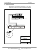
FS-8700-17 Optomux Driver Manual 3 Hardware Connections The FieldServer is connected to the OPTO22 device as shown below. Configure the OPTO22 device according to manufacturer’s instructions. - + - + - + - + COM - + - + - + - + COM - + - + - + - + COM FO FH TH TO * * PREVIOUS OPTOMUX * B1 OR B2 FO FO FH TH TO NEXT OPTOMUX * B1 OR B2 FH TH TO AC30A/B * B2 COMMUNICATION CONNECTIONS ARE MADE TO THE RACK (PB4AH, PA8AH OR PB16AH), NOT TO THE BRAIN BOARD.
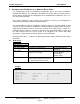
FS-8700-17 Optomux Driver Manual 4 Configuring the FieldServer as a Optomux Driver Client For a detailed discussion on FieldServer configuration, please refer to the FieldServer Configuration Manual. The information that follows describes how to expand upon the factory defaults provided in the configuration files included with the FieldServer (See “.csv” files on the driver diskette).
FS-8700-17 Optomux 4.
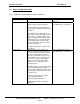
FS-8700-17 Optomux 4.4 Driver Manual Client Side Map Descriptors 4.4.1 FieldServer Related Map Descriptor Parameters Column Title Map_Descriptor_Name Function Name of this Map Descriptor Data_Array_Name Name of Data Array where data is to be stored / retrieved in the FieldServer. Legal Values Up to 32 alphanumeric characters One of the Data Array names from “Data Array” section above The use of this array is dependent on the Optomux command used in the map descriptor.
FS-8700-17 Optomux Da_Byte_Name* Driver Manual Names a data array that the driver will use to store poll/query response status data. Data_Array_Offset One data element is used per map descriptor. The element is determined by the Data_Array_Offset parameter. Starting location in Data Array Function Function of Client Map Descriptor 4.4.
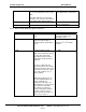
FS-8700-17 Optomux Opto22_trigger* Driver Manual An optional parameter. If used then set the value of this parameter to yes or no and the da_byte_name parameter must be specified too. No, Yes When this parameter is set to yes then the Optomux driver processes this map descriptor differently from a normal wrbc or rdbc function. The driver processes the map descriptor at the scan interval specified. Each time that it is processed the driver checks the element of the da_byte_name data array specified.
FS-8700-17 Optomux Driver Manual the functions provided in table 6.1. Opto22_modifier1* The parameter must be spelled and spaced exactly as provided in the table. Leading and trailing spaces are not important but inter-word spaces are very important. Take care not to use tabs. A few Opto22_Functions require one ore more additional arguments. See Chapter 6.
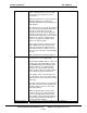
FS-8700-17 Optomux 4.4.4 Driver Manual Map Descriptor Example 1 – Read on/off Status In this example the on/off status of all module positions of the Optomux device are read and stored. They are read continuously (rdbc) every 5 seconds (Scan_Interval). The Read Status command returns one packed 16 bit value. There is one bit per module position, thus, if the returned value was 2 then this would indicate that the 2nd position is on and all other positions are off.
FS-8700-17 Optomux 4.4.5 Driver Manual Map Descriptor Example 2 – Read On/Off Status (Data stored differently) This example reads the same data as the previous example. The difference is that the data is stored differently. In this example the data is unpacked and stored in 16 consecutive data array elements – one element per module position.
FS-8700-17 Optomux 4.4.6 Driver Manual Map Descriptor Example 3 – Command Response/Completion Status We use example 1 to show how it can be modified to get the driver to expose the response / status generated when the command was executed. The response / status values indicate the success / failure of the command based either on the driver’s ability to complete the command OR on the ack/nack returned by the device.
FS-8700-17 Optomux 4.4.7 Driver Manual Map Descriptor Example 4 – Triggered Action This example shows the elements necessary to generate a triggered poll. Even though this map descriptor appears to write to the device continuously the driver recognizes the opto22_trigger parameter and based on its value will only send the poll when the trigger value is set.
FS-8700-17 Optomux 4.4.8 Driver Manual Map Descriptor Example 5 – Using Address and Length to tell the FieldServer which module positions to access. This example shows a map descriptor which reads analog inputs from an Optomux Device. The address and length tell the driver which inputs to read. Take care to ensure that the data array used for storage has a data format suitable for storing the data type returned by the command. In this case an unsigned integer at least 16 bits long ( eg UINT16 or FLOAT).
FS-8700-17 Optomux 4.4.9 Driver Manual Map Descriptor Example 6 – Using a Mask to Address specific module positions There may be occasions when it is not suitable to use address and length. For example if you are attempting to address non-consecutive Optomux module positions OR when you wish to use a command that affects all module positions. The driver provides an alternate method for module position specification by allowing you to specify a mask as a parameter in the CSV file.
FS-8700-17 Optomux Driver Manual 4.4.10 Map Descriptor Example 7 – Specifying Module Positions Dynamically Previous examples addressed module positions statically. This example illustrates how you can use a data array’s value to specify the module position’s to be affected by a command. As data arrays can have their values changed by remote devices, the module position specification may be changed dynamically. The CSV file does not require editing.
5 Configuring the FieldServer as a Optomux Server The FieldServer does not support the emulation of an Optomux server at present. FieldServer Technologies 1991 Tarob Court, Milpitas, California 95035 (408) 262-2299 fax: (408) 262-9042 Visit our website: www.fieldserver.com E-mail: support@fieldserver.
FS-8700-17 Optomux Driver Manual 6 Driver Notes 6.1 Data_Array_Name, DA_Bit_Name, DA_Byte_Name These parameters are used to specify data array names. Despite their names a data array of any Data_Format can be used for any of these parameters. This driver uses DA_Byte_Name exclusively as a location for the commands to trigger map descriptors and in which to store poll response status.
FS-8700-17 Optomux Driver Manual 255 the Optomux literature should be read for additional information as these are codes returned by the Optomux device. 128 129 130 131 132 133 134 135 Nak from Optomux Device. Power Up Clear Expected. Command Ignored. Nak from Optomux Device. Undefined Command Nak from Optomux Device. Checksum Error Nak from Optomux Device. Input Buffer Overun Nak from Optomux Device. Non Printable Ascii character received Nak from Optomux Device.
FS-8700-17 Optomux COMMAND NAME Read/ Write/ Both Driver Manual OPTO22_FORMAT MASTER LENGTH OPTION CONSIDERED (See Notes) NOTES w POWER UP CLEAR 4 w RESET 4 w SET TURN-AROUND DELAY 4 w SET WATCHDOG DELAY 4 w SET WATCHDOG DELAY (Analog) 3 w SET PROTOCOL 4 r IDENTIFY Optomux TYPE 4 w SET ENHANCED DIGITAL WATCHDOG 3 w SET ENHANCED ANALOG WATCHDOG 1 w SET TIMER RESOLUTION Uses up to Length (max=16) array elements.
FS-8700-17 Optomux Read/ Write/ Both COMMAND NAME Driver Manual OPTO22_FORMAT MASTER LENGTH OPTION CONSIDERED (See Notes) w SET LATCH OFF TO ON 3 w SET LATCH ON TO OFF 3 r READ LATCHES 1 2 b READ AND CLEAR LATCHES 1 3,2 w CLEAR LATCHES 3 w START/STOP COUNTERS 3 w START COUNTERS 3 w STOP COUNTERS 3 r READ COUNTERS 1 b READ AND CLEAR COUNTERS 1 w CLEAR COUNTERS 3 w SET TIME DELAY 3 w INITIATE SQUARE WAVE 3 w HIGH RESOLUTION SQUARE WAVE 3 w RETRIGGER TIME DELAY
FS-8700-17 Optomux Read/ Write/ Both COMMAND NAME Driver Manual OPTO22_FORMAT MASTER LENGTH OPTION CONSIDERED (See Notes) w START ON PULSE 3 w START OFF PULSE 3 w SET TRIGGER POLARITY 3 w TRIGGER ON POSITIVE 3 w TRIGGER ON NEGATIVE 3 r READ PULSE COMPLETE BITS r READ DURATION COUNTERS 3 b READ AND CLEAR DURATION COUNTERS 3 w CLEAR DURATION COUNTERS 3 w WRITE ANALOG OUTPUTS 3 r READ ANALOG OUTPUTS 3 w UPDATE ANALOG OUTPUTS 3 r READ ANALOG INPUTS 3 1 2 NOTES affec
FS-8700-17 Optomux Read/ Write/ Both r COMMAND NAME Driver Manual OPTO22_FORMAT MASTER LENGTH OPTION CONSIDERED (See Notes) READ AND AVERAGE INPUT 4 w START INPUT AVERAGING 3 r READ AVERAGE COMPLETE BITS r READ INPUT AVERAGE DATA 3 r READ TEMPERATURE INPUTS 3 r READ AVERAGE TEMPERATURE INPUTS 3 w SET INPUT RANGE 3 r READ OUT-OF-RANGE LATCHES 4 b READ AND CLEAR RANGE LATCHES 3 w CLEAR OUT-OF-RANGE LATCHES 4 r READ LOWEST VALUES 3 w CLEAR LOWEST VALUES 3 b READ AND CLEA
FS-8700-17 Optomux Read/ Write/ Both COMMAND NAME Driver Manual OPTO22_FORMAT MASTER LENGTH OPTION CONSIDERED (See Notes) NOTES affected by command. b READ AND CLEAR PEAK 3 r CALCULATE OFFSETS 1 w SET OFFSETS 1 r CALCULATE AND SET OFFSETS 1 r CALCULATE GAIN COEFFICIENTS 1 w SET GAIN COEFFICIENTS 1 r CALCULATE AND SET GAIN 1 w SET OUTPUT WAVEFORM R 4 w IMPROVED OUTPUT WAVEFORMS 4 Only specified module positions get read and cleared.
FS-8700-17 Optomux 6.5 Driver Manual Driver Stats In addition to the standard FieldServer communication statistics described in the FieldServer User’s Manual the Optomux Driver can also expose some driver statistics by writing data to a data array. A special map descriptor is required. The driver recognizes the map descriptor by its name which must be "opto22-stats" . The following example shows how this special map descriptor can be configured.
FS-8700-17 Optomux 7 Driver Manual Revision History Date Resp Format Driver Ver. 2/18/04 JD MF 0 Doc. Rev. 1 Comment Releasing FieldServer Technologies 1991 Tarob Court, Milpitas, California 95035 (408) 262-2299 fax: (408) 262-9042 Visit our website: www.fieldserver.com E-mail: support@fieldserver.