A Sierra Monitor Company Driver Manual (Supplement to the FieldServer Instruction Manual) FS-8700-102 Honeywell Zellweger IR-148 Manual APPLICABILITY & EFFECTIVITY Effective for all systems manufactured after May 1, 2001 Driver Version: 1.
FS-FS-8700-102 Honeywell Zellweger IR-148-8_8-Channel Manual Table of Contents TABLE OF CONTENTS 1. 2. HONEYWELL ZELLWEGER IR-148 DESCRIPTION...................................................... 3 DRIVER SCOPE OF SUPPLY ........................................................................................ 4 2.1. Supplied by FieldServer Technologies for this driver.................................................. 4 2.2. Provided by the Supplier of 3rd Party Equipment ..................................
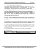
FS-8700-102 Honeywell Zellweger IR-148-8_8-Channel Manual 1. Page 3 of 19 Honeywell Zellweger IR-148 Description The Honeywell Infrared Gas Monitor (Model IR-148) detects solvents and gases such as HCFCs, HFCs and PFCs. IR-148 can have 1, 4 or 8 sampling points. This InfraTox driver reports gas values, alarms and troubles from IR-148 having either 1 or 8 sampling points. The serial driver can emulate a client or a server. The FieldServer and IR-148 device are connected using a RS-485 network.
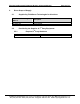
FS-8700-102 Honeywell Zellweger IR-148-8_8-Channel Manual 2. Page 4 of 19 Driver Scope of Supply 2.1. Supplied by FieldServer Technologies for this driver FieldServer Technologies PART # FS-8917-16 FS-8700-102 Description RJ45 to terminal connector cable. Driver Manual. Provided by the Supplier of 3rd Party Equipment 2.2. 2.2.1. Part # Required 3rd Party Hardware Description NONE FieldServer Technologies 1991 Tarob Court Milpitas, California 95035 USA Web:www.fieldServer.
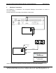
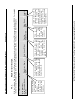
FS-8700-102 Honeywell Zellweger IR-148-8_8-Channel Manual 3. Page 5 of 19 Hardware Connections The FieldServer is connected to the Honeywell Zellweger IR-148 Device as shown in connection drawing.
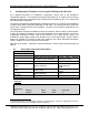
FS-8700-102 Honeywell Zellweger IR-148-8_8-Channel Manual 4. Page 6 of 19 Configuring the FieldServer as a Honeywell Zellweger IR-148 Client For a detailed discussion on FieldServer configuration, please refer to the FieldServer Configuration Manual. The information that follows describes how to expand upon the factory defaults provided in the configuration files included with the FieldServer (See “.csv” sample files provided with the FieldServer).
FS-8700-102 Honeywell Zellweger IR-148-8_8-Channel Manual 4.2.
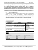
FS-8700-102 Honeywell Zellweger IR-148-8_8-Channel Manual Page 8 of 19 Example // Client Side Nodes Nodes Node_Name, DEV1, 4.4. Node_ID, 1, Protocol, InfraTox, Port R1 Client Side Map Descriptors 4.4.1. FieldServer Related Map Descriptor Parameters Column Title Map_Descriptor_Name Data_Array_Name Data_Array_Offset Function 4.4.2.
Map Descriptor Example. Page 9 of 19 The Driver stores Data from device (DEV1) with this memory location as the starting point and onward, in Data Array DA_R1. This means that the FieldServer cannot poll the target device but monitors the device. Extracted data from incoming messages are stored in Data Array DA_R1 Data_Array_Offset, 0, This is the logical name of the target device having the parameters defined in section 4.3.
FS-8700-102 Honeywell Zellweger IR-148-8_8-Channel Manual 5. Page 10 of 19 Configuring the FieldServer as a Honeywell Zellweger IR-148 Server For a detailed discussion on FieldServer configuration, please refer to the FieldServer Configuration Manual. The information that follows describes how to expand upon the factory defaults provided in the configuration files included with the FieldServer (See “.csv” sample files provided with the FieldServer).
FS-8700-102 Honeywell Zellweger IR-148-8_8-Channel Manual 5.2. Page 11 of 19 Server Side Node Descriptors Section Title Nodes Column Title Function Node_Name Provide name for node Commonly used parameter but irrelevant for this driver as Protocol is node-less.
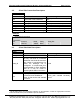
FS-8700-102 Honeywell Zellweger IR-148-8_8-Channel Manual 5.3.2. Page 12 of 19 Driver Specific Map Descriptor Parameters Column Title Function Legal Values One of the node names Name of Node to which data Node_Name specified in “Server Node has to be sent. Descriptor” - section 5.2 1-Maximum of Data Array Length Length of Map Descriptor length. Name of Data Array used to One of the Data Array lock the sensor.
Map Descriptor Example 1 Server using Data Array: Page 13 of 19 Driver will look into this data array to send Zellweger message to Zellweger 8 Channel Client. This wrbc function makes this Server an Active Server. This Server continuously sends data for each sensor. Data_Array_Offset, 0, Length, 100, Length should be sufficient to allow Server to store data for all sensors for a Node. Node_Name, DEV1, Server sends data to this Node connected to FieldServer.
Map Descriptor Example 2: - Server using INI file: Page 14 of 19 This wrbc function makes this Server an Active Server. This Server continuously sends data from the specified line from SMD1.ini file. Function, wrbc, Length 1, Length should be set to 1. Node_Name DEV1, Server sends data to this Node connected to the FieldServer. Data_Array_Offset, 2, Specifies the use of the INI file as the Data source.
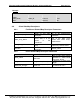
FS-8700-102 Honeywell Zellweger IR-148-8_8-Channel Manual Page 15 of 19 Appendix A. Advanced Topics Appendix A.1. Supported Functions at a glance Message Types Gas Value Message Trouble Message Blank Message Alarm Message Locked Point Message Other 49 byte messages beginning 0xb1 Other 49 byte messages Other messages Notes Message reports a gas value and units.
FS-8700-102 Honeywell Zellweger IR-148-8_8-Channel Manual Page 16 of 19 b) Extended storage : If the FieldServer is configured to use extended storage then data will be stored as below Offset Sensor Contents 0 1 Alarm or Trouble 1 2 1 1 Alarm Type Trouble 3 1 Gas Value 4 5 6 7 1 1 1 1 Gas Units Gas Units Gas Units State 8 1 Gas Value Valid 9 1 Gas Value Age 10 1 Sensor Data Age 11 1 I/O State 12 1 13 1 14 1 15 1 16 1 17 1 18 1 19 1 20 1 21 1 22-24 25..49 50.
FS-8700-102 Honeywell Zellweger IR-148-8_8-Channel Manual Page 17 of 19 Appendix A.3. Driver stats In addition to the standard FieldServer operating statistics the driver can expose certain key stats in a Data Array which can then be monitored by an upstream device. Adding the following to the configuration file will activate these stats for a driver configured as a Client. // Expose Driver Operating Stats.
FS-8700-102 Honeywell Zellweger IR-148-8_8-Channel Manual Page 18 of 19 Appendix B. Driver Error Messages Some configuration errors might produce an error every time a poll is generated. This will fill the error buffer quickly and not add any clarity. For this reason the driver suppresses subsequent similar messages. Thus it is possible for the same error produced by multiple Map Descriptors to produce only one error message. Subsequent error messages can be seen on the driver message screen.
FS-8700-102 Honeywell Zellweger IR-148-8_8-Channel Manual Page 19 of 19 THIS PAGE INTENTIONALLY LEFT BLANK FieldServer Technologies 1991 Tarob Court Milpitas, California 95035 USA Web:www.fieldServer.com Tel: (408) 262-2299 Fax: (408) 262-9042 Toll_Free: 888-509-1970 email: support@fieldServer.