FieldServer Technologies A Sierra Monitor Corporation Company 1991 Tarob Court, Milpitas, California 95035 USA Phone: (408) 262-2299 Toll Free: (888) 509-1970 Fax: (408) 262-2296 Email: support@fieldserver.com Web Site: www.fieldserver.
FS-RA-CLX_SlotServer_Instruction_Manual_(T17011) Table of Contents TABLE OF CONTENTS 1. 1.1. INTRODUCTION............................................................................................................. 4 About this product ...................................................................................................... 4 2.1. 2.2. 2.3. PRE-STARTUP CHECKLIST..........................................................................................
FS-RA-CLX_SlotServer_Instruction_Manual_(T17011) Table of Contents Appendix A.4. Dealing with ControlLogix RPI Settings........................................................26 Appendix A.5. Installing SlotServer on a Remote Rack using CNB Cards...........................27 Appendix A.5.1. Hardware and Software requirements....................................................27 Appendix A.5.2. Setup .....................................................................................................
FS-RA-CLX_SlotServer_Instruction_Manual_(T17011) 1. Page 4 of 34 Introduction 1.1. About this product The SlotServer Instruction Manual provides the information necessary to configure the SlotServer, allowing an Allen Bradley ControlLogix platform to pass data between a ControlLogix CPU and other third party communications protocols supported by the SlotServer. The SlotServer uses implicit communications between the CPU and the SlotServer and is consequently treated as an I/O Server in RSLogix.
FS-RA-CLX_SlotServer_Instruction_Manual_(T17011) 2. Page 5 of 34 Pre-Startup checklist 2.1. Accessories supplied with the SlotServer Please verify that the following components were supplied with the SlotServer module: FieldServer Technologies PART # Description 2-way combi-comb connector for LonWorks port Software CD CAT-5 Direct Ethernet Cable Documentation Binder 2.2.
FS-RA-CLX_SlotServer_Instruction_Manual_(T17011) 3. Page 6 of 34 Steps for implementation of a SlotServer Project 3.1. Read the SlotServer Instruction Manual This provides guidelines for getting started with the SlotServer, and is very useful for first time implementation of a SlotServer application. 3.2. Install the SlotServer in a ControlLogix Rack. Refer to Section 4 for information on installation. 3.3. • • • Write the SlotServer configuration.
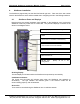
FS-RA-CLX_SlotServer_Instruction_Manual_(T17011) 4. Page 7 of 34 SlotServer Installation The SlotServer plugs directly into the AB1756 ControlLogix rack. Take note of the slot number used for the SlotServer as this will be needed when configuring the I/O in the RSLogix software. 4.1. SlotServer Ports and Displays Note that there are several hardware ports available on the SlotServer card, but that this SlotServer model only makes use of a select few.
FS-RA-CLX_SlotServer_Instruction_Manual_(T17011) Page 8 of 34 Communications Status LED’s LonSvc Run Node Off Conf Err Sys Err Com Err 10/100 Act Rx LED Run LonSvc NodeOff Conf Err Sys Err Com Err RS-485 (R1) Ethernet Lights (N1,N2) Tx Description When the SlotServer is powered up, this light will start flashing after approximately 2 minutes. If this light does not flash, it is an indication that the firmware is not running, and that the SlotServer will not be operating.
FS-RA-CLX_SlotServer_Instruction_Manual_(T17011) Page 9 of 34 TP/FT10 LonWorks connection This two wire connection is polarity insensitive and can be multi-dropped into a LonWorks Network. Ethernet Port The Ethernet port can be used for configuration and troubleshooting, as well as for Protocols that require an Ethernet connection. Use standard Ethernet cables for this connection. RS-485 Port This is a standard 2-wire RS-485 port. Specify as R1 in the configuration. 4.2.
FS-RA-CLX_SlotServer_Instruction_Manual_(T17011) 5. Page 10 of 34 SlotServer Topology The SlotServer connection varies based on the protocol being used. Refer to the appropriate driver supplement for more details. The diagram in section 4.1 shows the ports available on the SlotServer for each of the protocols. FieldServer Technologies 1991 Tarob Court Milpitas, California 95035 USA Web:www.fieldServer.com Tel: (408) 262-2299 Fax: (408) 262-2296 Toll_Free: 888-509-1970 email: support@fieldServer.
FS-RA-CLX_SlotServer_Instruction_Manual_(T17011) 6. Page 11 of 34 Configuring the CPU interface to the SlotServer 6.1. CPU interface Description The SlotServer Data Images (Data Arrays) share data with the ControlLogix CPU tags using the backplane for communication and the FieldServer Logix driver. To map the Logix Driver, the Driver needs to be configured in the SlotServer Configuration. The information that follows details the configuration parameters that can be used for this driver.
FS-RA-CLX_SlotServer_Instruction_Manual_(T17011) Page 12 of 34 Example // Data Arrays Data_Arrays Data_Array_Name, In_1, In_2, Out_1, Out_2, 6.4. Data_Array_Format, Float, Float, Float, Float, Data_Array_Length 76 76 76 76 Server Side Connection Descriptors Section Title Connections Column Title Adapter Function Adapter Name Legal Values ControlNet Example // Server Side Connections Connections Adapter ControlNet 6.5.
FS-RA-CLX_SlotServer_Instruction_Manual_(T17011) 6.6. Page 13 of 34 Server Side Map Descriptors 6.6.1. SlotServer Specific Map Descriptor Parameters Column Title Map_Descriptor_Name Scan_Interval Function 6.6.2. Function Legal Values Name of this Map Up to 32 alphanumeric Descriptor characters Rate at which IO image Use twice the rate used in data is updated RSLogix e.g. 0.
Map Descriptors Example Page 14 of 34 Function, WRBC, RDBC, Node_Name, SlotServer_CPU, SlotServer_CPU, IO_Data_Type, REAL, REAL, 4 Data_Format, Float, Float, Float, Float, Data_Array_Length 76 76 76 76 4 DA_Name_Start , In_1, Out_1, DA_Count, 2, 2, See the Data Arrays section for the maximum Data Array lengths allowed per IO_Data_Type chosen on the Map Descriptor. FieldServer Technologies 1991 Tarob Court Milpitas, California 95035 USA Web:www.fieldServer.
FS-RA-CLX_SlotServer_Instruction_Manual_(T17011) 7. Page 15 of 34 Programming the ControlLogix CPU for a small SlotServer Interface The discussion that follows describes the basic steps to set up and test the system for transferring data between CPU tags and the SlotServer using the I/O image method. The quick Start example uses LonWorks as the example 3rd Party Protocol. A hardcoded template is filled with Lon variables is created.
FS-RA-CLX_SlotServer_Instruction_Manual_(T17011) 7.2. • • Page 16 of 34 Step 2: Add and configure the SlotServer as an IO Module Right-click on I/O Configuration and select “New Module”. Choose the 1756-MODULE Choose the 1756-MODULE Be sure to choose the correct Slot number in the rack where your SlotServer reside Click Next and choose a RPI of 100 ms. This is the rate at which the I/O image data will be transferred FieldServer Technologies 1991 Tarob Court Milpitas, California 95035 USA Web:www.
FS-RA-CLX_SlotServer_Instruction_Manual_(T17011) Page 17 of 34 Click Finish to complete the Module Properties setup 7.3. • Step 3: Write Ladder Program to get Input Data from Data Arrays Add a CPS (Synchronous Copy File) Ladder element to synchronize the incoming Data from the Input Data Arrays. Use the Input Image Data as Source. You can create the Destination Tag by right clicking on Destination and choosing New Tag. FieldServer Technologies 1991 Tarob Court Milpitas, California 95035 USA Web:www.
FS-RA-CLX_SlotServer_Instruction_Manual_(T17011) Page 18 of 34 Create a Controller Tag of Type REAL, dimension of 80 for the Destination • • Add an EQU (Compare if equal) ladder element to check when the first Data Array has been received. The block number is at offset 2 of the input image. Finally, add another CPS ladder element to copy the LonWorks Data from the InData_Copy Tag to a new Controller Tag, called Lon_In_01. Also create the Tag by right clicking on Destination and choosing New Tag.
FS-RA-CLX_SlotServer_Instruction_Manual_(T17011) Page 19 of 34 Below is the final ladder program to access data from LonWorks Function Block In[0] Very Important Note! It is very important to first make a synchronous copy of the input image data before using it. If this is not done, the input data cannot be guaranteed to be from a specific SlotServer Data Array. FieldServer Technologies 1991 Tarob Court Milpitas, California 95035 USA Web:www.fieldServer.
FS-RA-CLX_SlotServer_Instruction_Manual_(T17011) 7.4. Page 20 of 34 Step 4: Write Ladder Program to Send Output Data to Data Arrays This step demonstrates how to write data to the Data Array Out[0] • • • Create a Controller Tag called Lon_Out_01 of type REAL[80]. Add a new rung to the Ladder program and add a MOV element to move a block number value of 1 into Lon_Out_01[2]. Finally add a CPS (Synchronous Copy File) element to copy the full Lon_Out_01 tag into the Output Image Tag.
FS-RA-CLX_SlotServer_Instruction_Manual_(T17011) 8. Page 21 of 34 Programming the ControlLogix CPU for larger SlotServer Interfaces The previous example is for accessing only one Data Array. The following steps describe how to access multiple Data Arrays. 8.1. Multiple Input Data Arrays In this example, we access Input Data Arrays In[1] up to In[24]. We simply add to the existing ladder program as shown in the Quickstart example.
FS-RA-CLX_SlotServer_Instruction_Manual_(T17011) Page 22 of 34 It is possible to add up to 65535 blocks. The update rate decreases as the number of blocks goes up. For 25 blocks we have an update rate of 25*RPI = 25*0.1 = 2.5 seconds. You can restrict the upcount to a certain value, e.g.2 by changing the Preset value of the CTU element. Very Important Note! It is very important to only update all the data of the Output Image Tag once using a Synchronous File Copy element.
FS-RA-CLX_SlotServer_Instruction_Manual_(T17011) Page 23 of 34 Appendix A. Advanced Topics Appendix A.1. Description of Data Transfer Process The data connection from the SlotServer to the Logix CPU consists of 496 bytes of input and 496 bytes of output data. Of the 2 Map Descriptors specified, the one with the WRBC function writes data to the Logix CPU filling its input data, and the one with the RDBC function accepts the Logix CPU’s output data.
Node Status Data Block Number Reserved 1 2 3 Node Status Data Block Number Reserved 1 2 3 79 ... 4 Protocol Type 0 Offset Description 79 ... 4 Protocol Type 0 Offset Description Out_x Data In_x Data Out_1 Out_2 Out_3 Out_4 .. Out_25 Output Data DeMultiplexer In_1 In_2 In_3 In_4 .. In_25 Input Data Multiplexer SlotServer Page 24 of 34 In [1] Out [0] Out [1] Output Data In [0] Out [24] In [24] External Device eg.
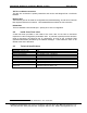
FS-RA-CLX_SlotServer_Instruction_Manual_(T17011) Page 25 of 34 Appendix A.2. The IO image header The IO image header appears at the start of every block of image data that is transferred to or from the SlotServer to the Logix CPU.
FS-RA-CLX_SlotServer_Instruction_Manual_(T17011) Page 26 of 34 Appendix A.4. Dealing with ControlLogix RPI Settings When setting up the SlotServer for ControlLogix, it is necessary to select the Request Packet Interval (RPI). The RPI is the rate at which data is transferred to and from the SlotServer IO buffers. The following factors need to be considered when deciding on an RPI: 1. Minimum RPI setting for the SlotServer is 100ms. 2.
FS-RA-CLX_SlotServer_Instruction_Manual_(T17011) Page 27 of 34 Appendix A.5. Installing SlotServer on a Remote Rack using CNB Cards Appendix A.5.1.
FS-RA-CLX_SlotServer_Instruction_Manual_(T17011) Appendix A.5.4. • • Page 28 of 34 RSNetWorx configuration Open up RSNetWorx and add the two CNB Cards to the Network by dragging them onto the Network in the Graph tab (Must be done with Edits Enabled). Follow the prompts on the screen to configure the Chassis being used, and the cards in each Chassis (Rack). Go Online with RSNetWorx, and then press “save”. This will transfer the RSNetWorx Configuration to the Keeper.
FS-RA-CLX_SlotServer_Instruction_Manual_(T17011) Appendix A.5.5. Page 29 of 34 Testing The SlotServer should now be visible to the CPU. Go Online with RSLogix and check the Input buffer of the SlotServer for data. A good check is to examine offset 2 of the input tag for a non-Zero value. If the SlotServer is multiplexing (DA_Count >1), then this value will be cycling through the Buffer numbers, otherwise if DA_Count=1, then offset 2 will be fixed at 1.
FS-RA-CLX_SlotServer_Instruction_Manual_(T17011) Appendix A.5.6. ControlNet • • Page 30 of 34 Connection limitations -Controlling the SlotServer using Only one remote I/O rack is supported. I/O can only be added online using a direct connection. The following Vendor information provides clarification: FieldServer Technologies 1991 Tarob Court Milpitas, California 95035 USA Web:www.fieldServer.com Tel: (408) 262-2299 Fax: (408) 262-2296 Toll_Free: 888-509-1970 email: support@fieldServer.
FS-RA-CLX_SlotServer_Instruction_Manual_(T17011) Page 31 of 34 Appendix A.6. Rules for Naming Logix driver Data Arrays Unlike most other FieldServer drivers, the Logix driver attaches significance to the name of the Data Array used in the Logix Driver Map Descriptor. This is done to allow the user to easily declare a series of Data Arrays to be multiplexed through the input and output buffers of the SlotServer.
Function, WRBC, RDBC, RDBC, RDBC, Example 2: Illegal Map Descriptors: Map_Descriptors Map_Descriptor_Name, Scan_Interval, Input_BP_Image, 0s, Output_BP_Image, 0s, Output_BP_Image2, 0s, Output_BP_Image3, 0s, Node_Name, CPU1, CPU1, CPU1, CPU1, Node_Name, CPU1, CPU1, IO_Data_Type, INT, INT, INT, INT, IO_Data_Type, INT, INT, Page 32 of 34 DA_Name_Start, Test_05, Test, Test_-3, Test6, DA_Name_Start, Test_5, Test_3, FieldServer Technologies 1991 Tarob Court Milpitas, California 95035 USA Web:www.
FS-RA-CLX_SlotServer_Instruction_Manual_(T17011) Page 33 of 34 Appendix B. Troubleshooting tips Appendix B.1. Things to check when communications fail. • • • Check for loose cabling on the third party network Verify that the correct program is loaded to the CPU Verify that the correct data types for the tags have been used. FieldServer Technologies 1991 Tarob Court Milpitas, California 95035 USA Web:www.fieldServer.
FS-RA-CLX_SlotServer_Instruction_Manual_(T17011) Page 34 of 34 THIS PAGE INTENTIONALLY LEFT BLANK FieldServer Technologies 1991 Tarob Court Milpitas, California 95035 USA Web:www.fieldServer.com Tel: (408) 262-2299 Fax: (408) 262-2296 Toll_Free: 888-509-1970 email: support@fieldServer.